Project LoD (Library of Designs)
In a sustainable future it is necessary to create shorter cycles for reuse of materials such as wood and bio plastic. One of the possible cycles is direct recycling by local or home manufacturers. Machines such as 3D printers, CNC milling machines and laser cutters are currently experiencing a rapid technical evolution, so that more and more user-friendly devices will be available in the near future.
OpenSCAD is a script-based open-source CAD program (Computer Aided Design) which, with its very simple syntax, enables anyone interested to create their own designs.
OpenSCAD course part 1 uses examples and group exercises to teach the basics to model your own designs in OpenSCAD. The syntax of the modeling language of OpenSCAD fits on an A4 page and is very easy to understand.
The course does not require any programming language skills. The syntax is so close to human understanding that it doesn't even need a computer to create blueprint drawings from it.
Preparation
There are minimum 3 ways you can work with OpenSCAD:
- For the course we need to install OpenSCAD on your PC / Laptop. It is available for Linux, Mac and Windows. Download OpenSCAD for your platform and install it.
- There is an limited version for an Android device called ScorchCAD available, in case you would like to work with this.
- Another possibility is an online version called OpenJSCAD, that does not need any installation.
1.1. Why using code to create 3D objects?
- Sharing functionality >> In all modern development languages there is always a way to take advantage of previous work and even someone else's work, sometimes its inheritance, sometimes is using a library.
- Making structural changes to existing parts >> With parametric design using variables you easily can adjust and modify existing designs.
- Straight forward from sketch to object >> Code is a way of defining exactly how you want things to happen in a specific order.
- Reusing things >> OpenSCAD has a very useful set of functionality called “modules”. A module is a lot like a method or a function in every-day c-based languages. With a module I can say “make this thing”, make a bunch of basic changes and call that module as many times as I like and augment the outcome.
- Learn basics of coding >> The practical usage of objects created with OpenSCAD scripts introduces you to the basics, that is essential to learn any computer language.
- Increases problem solving skills >> An algorithmic approach in creating a design helps generally in problem solving in daily life, as it helps you to learn how to think constructive.
1.2. What is OpenSCAD?
- OpenSCAD is a 2D/3D modeling software which is based on a functional programming language used to create solid 3D CAD (computer-aided-design) objects that can be previewed on the screen, and rendered into 3D mesh which allows the model to be exported in a variety of 2D/3D file formats
- It is free software and available for Linux/UNIX, MS Windows, Apples OS X, Android, and as an online browser application called OpenJSCAD
- Unlike most free software for creating 3D models e.g. Blender or FreeCAD, it creates 3D Models via a human-readable code, that makes it possible to actually create blue prints without using a computer.
- OpenSCAD is something like a 3D-compiler that reads in a script file that describes the object and renders the 3D model from this script file
- OpenSCAD allows a designer to create accurate 3D models and parametric designs that can be easily adjusted by changing parameter
- OpenSCAD can export 3D Models as STL, DXF, SVG, and/or as PNG
- FreeCAD has an excellent importer for .scad files, so you can assemble all parts and create technical documentations, as well as implementing OpenSCAD Designs in complex projects e.g. house designs
Cons vs Pro
Cons
- It is difficult to navigate objects in the preview port
- It can not render with Shaders for realistic renderings
- It is painstaking to do animation with it
- Assembly of several parts is also not easy
Pros
- Software is light-weight
- Code as text format has much smaller file size
- It is so easy to read, that you don't need a computer to create blueprints from it
- It is perfect for designer and makers, that create less complex product
1.3. How does OpenSCAD work?
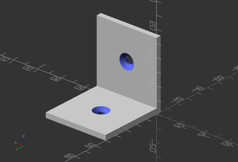
OpenSCAD is based on CSG, or Constructive Solid Geometry. It represents an object by combining basic shapes in a particular hierarchy of mainly Boolean operations.
This operations can be explained as follows:
- NOT can be expressed as every point that is inside polygon A but not inside B, and vice versa, effectively performing a subtraction of one from the other, known as difference.
- OR can be expressed as every point that is inside either polygon A or B, therefor also known as union.
- AND can be expressed as every point that is inside of both polygons A and B and thus represents the intersection of A and B.
- XOR can be expressed as every point that only lies in either polygon A or B, leaving out all points that lie on the intersection of A and B.
OpenSCAD uses following syntax principles, that we will learn piece-by-piece in this course:
object();
variable = value;
operator() action();
operator() { action(); action(); }
operator() operator() { action(); action(); }
operator() { operator() action(); operator() { action(); action();
Objects
- are building blocks for models, created by 2D and 3D primitives
- end in a semicolon ( ; )
Actions:
- statements include creating objects using primitives and assigning values to variables
- end with a semicolon ( ; )
Operators:
- or transformations, modify the location, color and other properties of Objects
- of different kinds can be used for the same action or group of actions
- closest to the action are processed first
- do not end with a semicolon ;
Values:
- are Numbers e.g. 42, a Boolean e.g. true, a String e.g."foo", a Range e.g.[0:1:10], or the Undef value e.g. undef
- can be stored in variables, passed as function argument, or returned as function result
!Lets get started, first lets look at the software graphical interface first!
2.1. Graphical user interface
The user interface of the OpenSCAD graphical application has 3 main windows: Text Editor, Console Window, and the viewing area/display window.
Text Editor
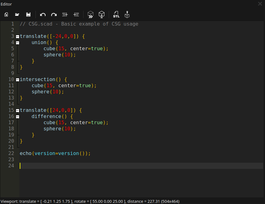
The text editor provides basic editing features like text search & replace CTRL + F, including syntax highlighting. Predefined color schemes can be changed via the Preferences dialog.

Text editor symbols (left to right):
- Create a new file CTRL + N
- Open an existing file CTRL + O
- Save the current file CTRL + S
- Undo the last step (CTRL + Z)
- Redo the undone (CTRL + SHIFT + Z)
- Unindent a row or selected block (CTRL + SHIFT + I)
- Indent a row or selected block (CTRL + I)
- Execute code in preview mode F5
- Execute code in render mode F6
- Export rendered object (F6 need to be pressed first) as STL file
- Send a rendered object directly to a connected printer or to OctoPrinta print management platform)
Preview Area
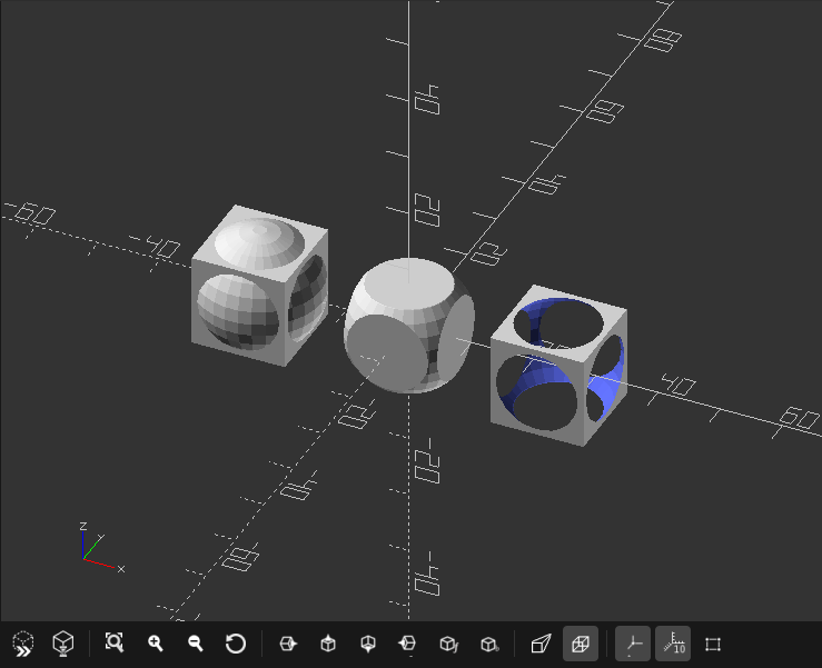
The 3D port shows a preview or rendered version of the design described in the text editor.
It is possible to easily change perspective and move around the object.
However, in order move the object within the space, you will need to use translate() or rotate().

Preview area symbols (left to right):
- Execute code in preview mode F5
- Execute code in render mode F6
- View all objects created by the code CTRL + SHIFT + V
- Zoom in
- Zoom out
- Reset view to offset
- Jump to right view CTRL + 7
- Jump to top view CTRL + 4
- Jump to bottom view CTRL + 5
- Jump to left view CTRL + 6
- Jump to front view CTRL + 8
- Jump to back view CTRL + 9
- Change to perspective view
- Change to orthographic view
- Switch on/off axis CTRL + 2
- Switch on/off scale markers in millimeters
- Shows wire frame of polygons, that creates the object CTRL + 1 >> !Only works in preview mode F5!**
Console window
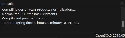
The console view shows important status information, warnings and errors.
Orientation in Preview 3D port
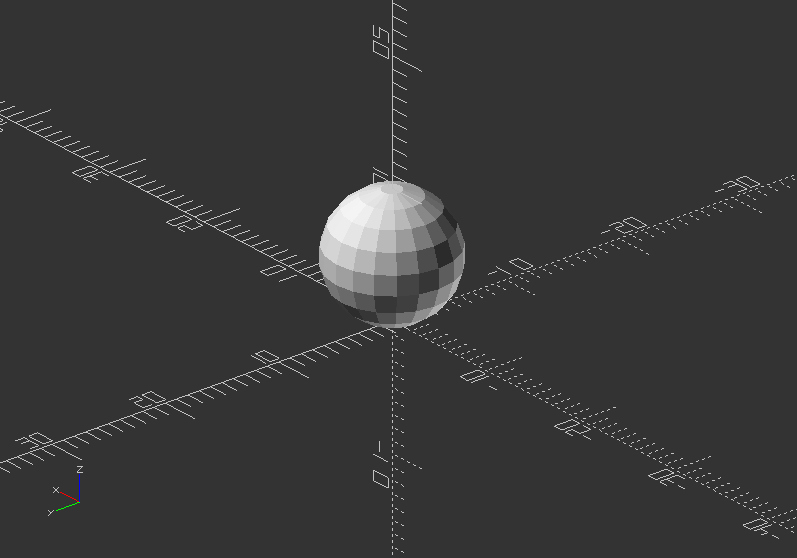
To show you, how to move around an object within the 3D view port, lets create our first object and preview it.
- Enter following code in the text editor:
sphere(30);
Do not forget a semicolon at the end!
- Press F5
Now follow the instruction to learn how to move around in the 3D space of the preview port.
- Move the mouse cursor over the viewing area and press LMB (Left Mouse Button) and drag the mouse to rotate in three-dimensional space around the object
- Press MMB (Middle Mouse Button) and drag the mouse to zoom towards are away from the object. You also can use the scroll wheel, if you have one.
- Now press the RMB (Right Mouse Button) and drag the mouse to shift the view in a two-dimensional way.
- Change the window sizes by moving with the cursor over the edges till the symbol changes, click the LMB and drag the window edge
The following characters used in front of a coded row will help your in the designing process, and opens the possibility to highlight or single out a part of the design.
| | | | --- | --- | | Character | Preview option | | * | Disable the object | | ! | Shows only this object | | # | Highlight the object | | % | Make the object transparent | | | |
Exercise:
- Write 3 lines code:
cylinder(40);,sphere(30);, andcube(35);in each row - Press F5
- Then add different modifying characters in front of a line
- Press F5 again
Example:
sphere(30);
cylinder(40);
%sphere(30);
#cube(35);
2.10. Export
- OpenSCAD provides different Export Formats.
- To export the F6 button need to be pressed to render the object first.
- 3D Formats are STL(recommended), OFF, AMF, 3MF, CSG.
- 2D Formats are DXF, SVG, PNG Image.
- In order to export objects as 2D format (DXF or SVG), projection() has to be used.
2.11. Import
- Import is achieved by the command import()
- OpenSCAD supports currently STL, OFF, AMF, and 3MF 3D formats, and DXF, SVG 2D formats
- If you want to import another SCAD file, you need to use include
instead - If you want to import an image, you can use surface()
- Parameters of import() are:
file >> This is the path to the file including filename (String). It is not absolute, but the relative path to the importing script. When using include<> with a script that uses import(), it is relative to the script using include<>
convexity >> Only used for optimize visualization in preview mode (Integer)
layer >> DXF only, it imports only a particular layer (Integer)
surface()
- Reads Height-map information from text or an image. It can read PNG files
- Parameters of surface() are:
file >> The path to the file, that contains the height-map data (String)
center >>This determines the positioning of the generated object (Boolean - default: false). If true, object is centered in X- and Y-axis. If false, object is placed in the positive quadrant
invert >> Inverts how the color value of images is translated to height (Boolean - default: false)
convexity >> Convexity parameter specifies the maximum number of front sides, or back sides (Integer). A ray intersecting the object might penetrate. This is only used for better preview, when pressing F5, it has no effect on F6.
Exercise:
Create your own busines card or other text graphics in 2D. If you want to use a image to the text, use import. After you finished, export it in dxf format!
import()
Follow the next steps in order to learn how to import an STL files!
- Go to your workshop folder (you did save your files in one folder, right!?)
- Create a folder called files
- Save following file into your files folder >> PotFace
- Use following code in your .scad file
import("files/potFace.stl");
Exercise:
Import your design! First, export it as stl. Then import it again via import()
Import SVG Vector Graphics
Before, download the file BunnySkull, and save it into the same files folder
Import an SVG Format and extrude it into a 3D shape:
linear_extrude(height=5, center=true, convexity=10)
translate([-107, -130, 0]) //It gets the graphic in offset of the coordinate system
import("files/bunnySkull.svg");
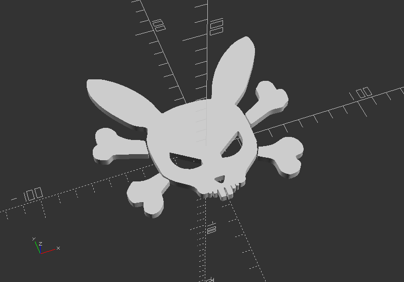
Note: you can use Inkscape, another open-source software to create your own graphics in SVG Format
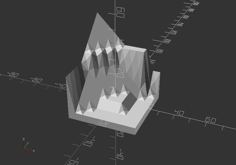
surface() - Import Height-map from a height-map text file:
Again, use this Link to download the text file of height-map data, and save it into your files folder.
scale(5)
rotate([0, 0, -90])
surface(file="files/surface.dat", center=true);
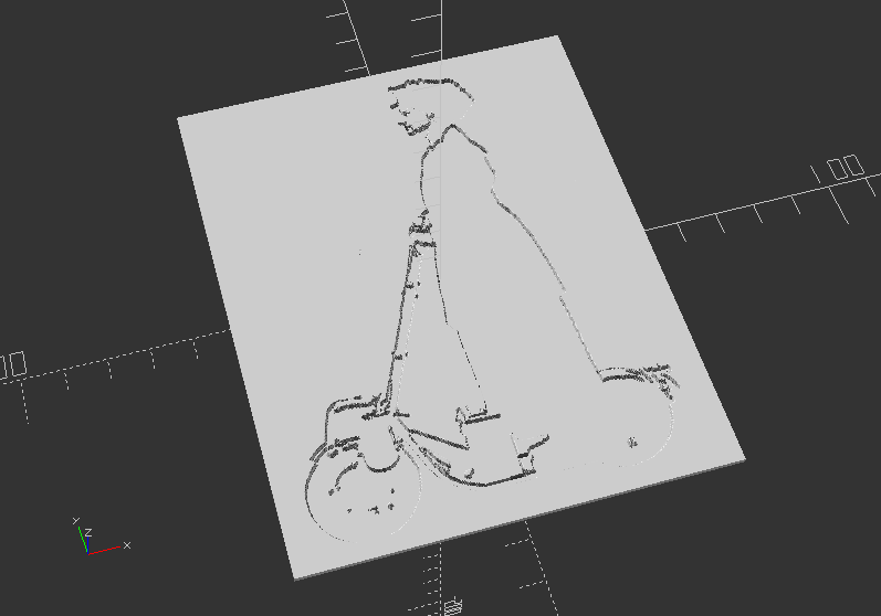
Surface - Import Height-map via an image with PNG format
Download the PNG picture file here, and save it into your files folder.
scale([0.2, 0.2, 0.012])
translate([0, 0, 12])
surface(file="files/escooter_1920.png", center=true);
2.12. Loops
- Loops are Iterator Functions used as an operator in OpenSCAD (no semicolons)
- A for() loop evaluate each value in a range of vectors, applying it to the following action
- It builds a tree of objects, one branch for each time
- Default syntax of for() is:
for(variable=[start:incement:end]) {action() object();} or action;
for(variable=[start:end]) {action() object();} or action;
for(variable=[vector]) {action() object();} or action;
- Parameters of for() are:
start >> Initial value (Integer)
increment >> Amount to increase the value (optional Integer - default=1)
end >> Stop when next value would be past end
- An intersection_for() loop iterates over the values in a range of vector and create the intersection of objects created by each pass
- Besides creating separate instances for each pass, the standard for() also groups all these instances
- Creating an implicit union, while intersection_for() works around the implicit union getting a result.
- By using a combination of the standard for() and intersection() statements
- intersection_for() loop uses the same parameters then for() loop
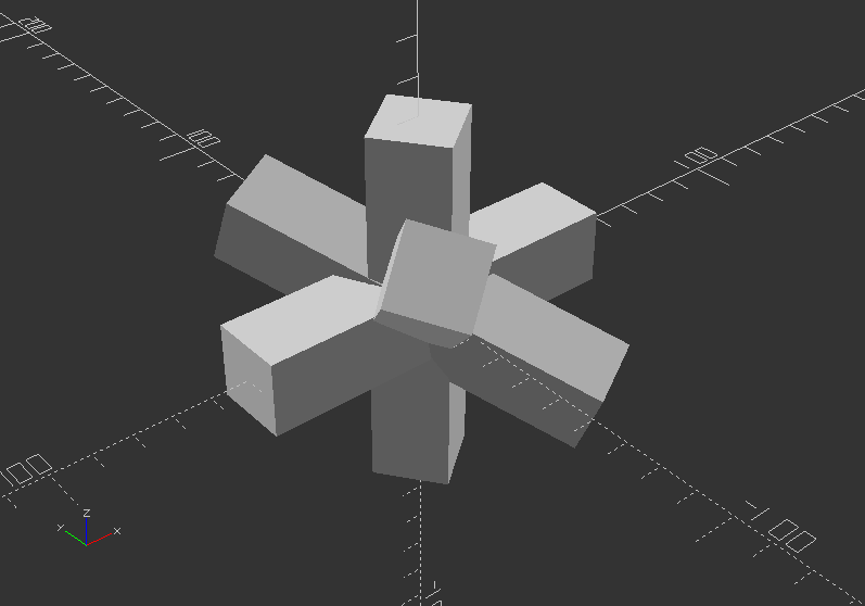
Loops: Iteration over a vector of vectors (rotation):
for(i=[[0, 0, 0], [10, 20, 300], [200, 40, 57], [20, 88, 57]]) {
rotate(i)
cube([100, 20, 20], center=true);
}
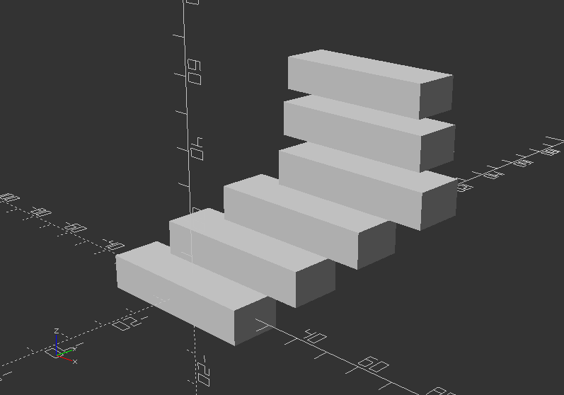
Loops: Iteration over a vector of vectors (translation)
for(i=[[0, 0, 0], [10, 12, 10], [20, 24, 20], [30, 36, 30], [20, 48, 40], [10, 60, 50]]) {
translate(i)
cube([50, 15, 10], center=true);
}
Intersection loop 1:
Loop over a range with a cutout of overlapping translated spheres as a result
intersection_for(n=[1:6]) {
rotate([0, 0, n*60])
translate([20, 0, 0])
sphere(r=40);
}
Intersection loop 2:
Loop over a range with a cutout of overlapping rotated blocks as a result
intersection_for(i=[[0, 0, 0], [10, 20, 300], [200, 40, 57], [20, 88, 57]]) {
rotate(i)
cube([200, 40, 40], center=true);
}
2.13. Statements
- Statements are tests, that checks on a condition, whether or not to execute an action in a sub scope.
- The if() statement has following default syntax:
if(test) scope1
if(test) {scope1}
if(test) scope1 else scope2
if(test) {scope1} else {scope2}
- Parameters of if() are:
test >> Usually a boolean expression, but can be any value or variable (do not confuse = with ==)
scope1 >> One or more actions to take when test is true
scope2 >> One or more actions to take when test is false
- Conditional ? is a function that uses a test to determine which of 2 values to return
- The Syntax of conditional ? is: a = test ? TrueValue : FalseValue ;
- The parameters of ? are:
test >> Usually a boolean expression, but can be something different though
TrueValue >> The value to return when test is true
FalseValue >> The value to return when test is false (values can be numbers, strings, a vector)
or the Undefined value (undef)
STATEMENTS:
if() statements used for execute certain actions dedicated by a number
a=0;
b=0;
c=1;
x=0;
y=0;
z=0;
if (b==c) color("Red") cube([40, 10, 30]);
if (b<a) {color("Green") cube([20, 20, 10], center=true);
color("Yellow") cylinder(60, 10);}
if (a>b) translate([0, 50, 0]) color("SeaGreen") text("a is greater than b");
else if(a<b) color("Khaki") translate([0, 60, 0]) text("b is greater than a");
else color("Peru") translate([0, 40, 0]) text("b is equal to a");
if (a==4) echo("a is 4");
if (x&&y) {color("White") cube([10, 40, 5]); color("Black") cylinder(h=7, d=30);}
if (x!=y) {color("Orange") cube([20, 40, 5],center=true); color("Blue") cylinder(h=20, d=10, center=true);};
if (z) {color("SkyBlue") cylinder(40, 20, 10);} else {echo("z is 0");}
if ((b<5)&&(c>8)) {color("HotPink") cylinder(h=70, d=10, $fn=40);}


Go through each line and check on the result, while changing the values of a,b,x,y,z. Execute with F5!
Not for course, but more examples
Here some examples of conditional ?
a=1; b=2; c= a==b ? "a==b" : "a!=b" ;
TrueValue = true; FalseValue = false;
a=5; test = a==1;
echo( test ? TrueValue : FalseValue );
L = 75; R = 2; test = (L/R)>25;
TrueValue = [test,L,R,L/R,cos(30)];
FalseValue = [test,L,R,sin(15)];
a1 = test ? TrueValue : FalseValue ;
"a!=b"
false
[true, 75, 2, 37.5, 0.866025]
2.14. Modules
- Modules can be used to define objects or, using children(), define operators
- Once defined, modules are temporarily added to the language, similar to libraries in other languages
- Default usage: module_name(parameters) {actions}, where:
module_name >> is your name for the module. Try to pick something meaningful!
parameters >> Zero or more arguments. They can be assigned as default values and/or variables to be used in calls. Parameter are local, so they will not conflict with external variables with the same name
actions >> Nearly any statement valid outside a module can be included within a module, including function definitions, and other modules. Such functions and modules can be called only from within the enclosing module itself.
- The module variables can be externally assigned into a module, but not visa verse
- Modules do not return values to the outside
- Object Modules >> OpenSCAD object modules like 3D primitives are embedded modules, so they are good examples. Object modules need to end with a semicolon ";"
- Operator Modules >> Use of children() allows modules to act as operators applied to any or all the objects within this module instantiation. Operator modules do not need to end with a semicolon
- Children are indexed objects via integers from 0 to children-1
- OpenSCAD sets children to the total number of objects within the scope. Grouped objects are treated as 1
- Syntax use of children():
children(); //all children
children(index); //value or variable to select one child
children([start:step:end]); //select from start to end incremented by step
children([start:end]); //step defaults to 1 or -1
children([vector]); //selection of several children
Modules: Implementing variables that can be changed parametric, so the module call will change objects accordingly:
ColorBreak=[[0, ""],
[20, "lime"], // upper limit of color range
[40, "greenyellow"],
[60, "yellow"],
[75, "LightCoral"],
[200, "red"]];
Expense=[16, 20, 25, 85, 52, 63, 45];
//First we build a color bar, that will be nested into another module
module ColorBar(value,period,range) { // 1 color on 1 bar
RangeHi = ColorBreak[range][0];
RangeLo = ColorBreak[range-1][0];
color( ColorBreak[range][1] )
translate([10*period,0,RangeLo])
if (value > RangeHi) cube([5,2,RangeHi-RangeLo]);
else if (value > RangeLo) cube([5,2,value-RangeLo]);
}
Now the module, which is going to be called afterwards. Note, this will use the ColorBar module as parameter:
module ShowColorBars(values) {
for (month = [0:len(values)-1], range = [1:len(ColorBreak)-1])
ColorBar(values[month],month,range);
}
Call the module:
translate([-30, -20, 0])
ShowColorBars(Expense);
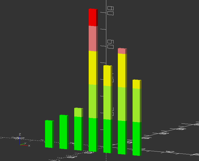
Now change the values in Expense=[] and press F5 again!
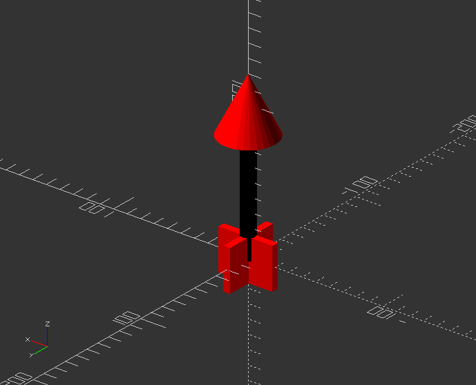
Example of rigged module
It is not possible to change this object parametric:
module arrow(){
color("Black") cylinder(100, 5, 5);
color("Red") cube([40, 5, 30], true);
color("Red") cube([5, 40, 30], true);
translate([0, 0, 100])
color("Red")
cylinder(40, 20, 0, true);
}
Call the simple module
arrow();
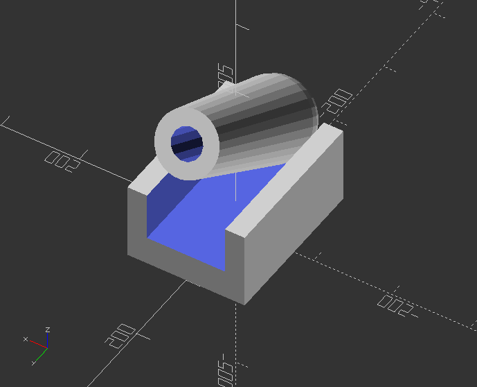
Create a module
size=5;
angle=30;
module cannon(size=10, angle=60) {
scale(size)
union() {
rotate([0, 0, 90])
translate([0, 0, 10])
difference() {
cube([40, 30, 20], true);
translate([0, 0, 5])
cube([50, 20, 15], true);
}
translate([0, -15, 20])
rotate([angle-90, 0, 0])
difference() {
union() {
sphere(10);
cylinder(40, 10, 8);
}
cylinder(41, 4, 4);
}
}
}
Call the module that has size and angle as variable:
cannon(size,angle);
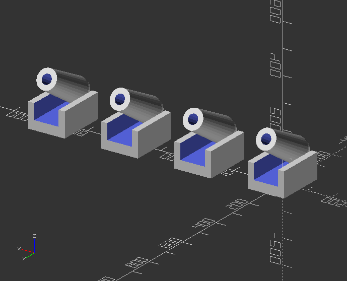
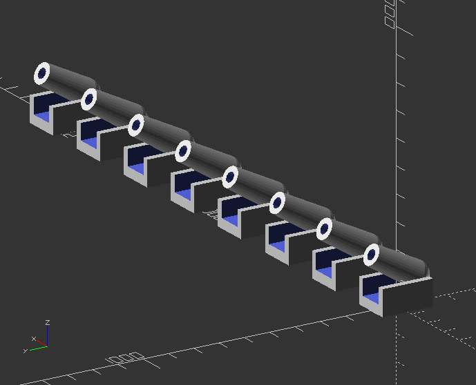
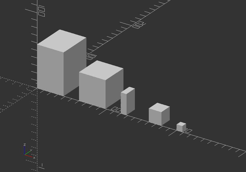
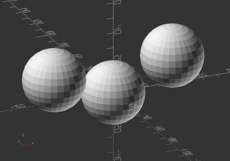
Modules >> Multiply objects along the x axis
module linear_array(count,distance) {
for(i=[0:1:count-1]) {
translate([distance*i, 0, 0])
children();
}
}
Call the array module:
linear_array(4, 300)
cannon(size, angle);
Difficult task: Change the linear_array to a x,y,z module by using if() loop!
Use integers to dedicate axis:
axis=0; //x: 0, y: 1, z: 2
module linear_array(axis,count,distance) {
//If value is 0, the axis is x
if(axis==0) {
//Loop it according to count value
for(i=[0:1:count-1]) {
//Translate children along x
translate([distance*i, 0, 0])
children();
}
}
//If value is 1, the axis is y
if(axis==1) {
//Loop it according to count value
for(i=[0:1:count-1]) {
translate([0, distance*i, 0])
children();
}
}
//If value is 2, the axis is z
if(axis==2) {
//Loop it according to count value
for(i=[0:1:count-1]) {
translate([0, 0, distance*i])
children();
}
}
}
Call the array module:
linear_array(0, 8, 300)
cannon(size, angle);
2.15. Variables
- Variables are like placeholders for values, that can contain numbers, strings, boolean values a.o.
- A variable has a name, which can be chosen freely, but should be meaningful to avoid later confusion.
- It will replace "hard coded" values, which are not parametric/interchangeable.
- If you use 100 object with a certain "hard coded" value, you need to change 100 values, while with variables only one value need to be changed.
- Using "hard coded" values is called static, and is in some cases good to use or even necessary.
- One the other hand using variables is parametric that offers flexibility of the design.
- Syntax usage: variable_name = value; i.e. object(variable_name);
- Each variable assignment need to end with semicolon ";"
EXERCISE:
- Change the hard numbers of your earlier design into variables.
- Create a module from your object, using the variable names.
- Call the module and test, if changing values has an effect on your design.
- Create another module, that will do translation and rotation in one call. Use tx,ty,tz,rx,ry,rz as variable names.
- Test if your object is moving and rotating by changing the values of your operation module.
2.2. Commenting code
Commenting the code is like leaving script notes for yourself and/or help others to understand
Comments are ignored by the compiler, that creates the preview or 3D mesh
It is also useful to create a header as Multi-line comment to add file name, description, author s.o.
Multi-line comments or commenting out blocks of code uses /* to comment in, while */ is used to comment out.
/*
Multiline comments
*/
Single lines can be commented by using two forward slashes.
//Single line comment
Single line comments can be automated by selecting the line or multiple lines and press CTRL + D. Press SHIFT + CTRL + D on a commented line or section to comment it out.
This will not work, if there is an empty line between the rows!
With a block selection you select all lines at once. Press SHIFT + CTRL + D to comment out. Press CTRL + D to comment it again.
//Commentline 1
//Commentline 2
//Commentline 3
2.3. Boolean operations
There are 3 Boolean Operations in OpenSCAD:
difference(),
- intersection(),
- and union().
!The chronological order of objects within the operators block is significant!
Try the code below and swap the positions of the objects!
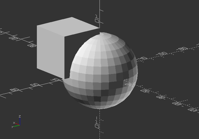
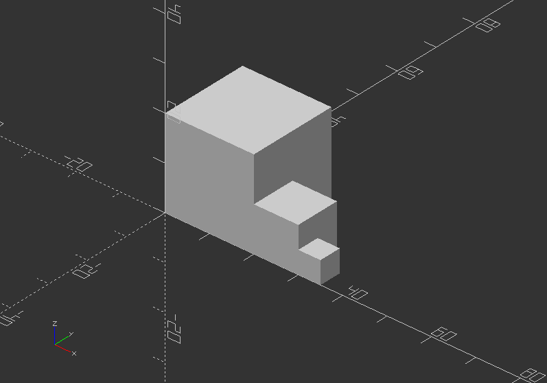
difference()
- creates a shape that cutouts the difference between 2 objects, or an object group.
- it substracts the 2nd object with the 1st object.
difference() {
sphere(30);
cube(35);
}
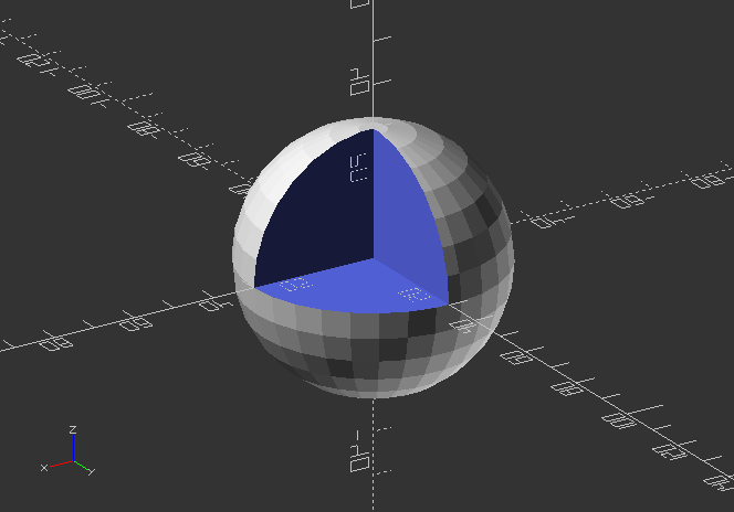
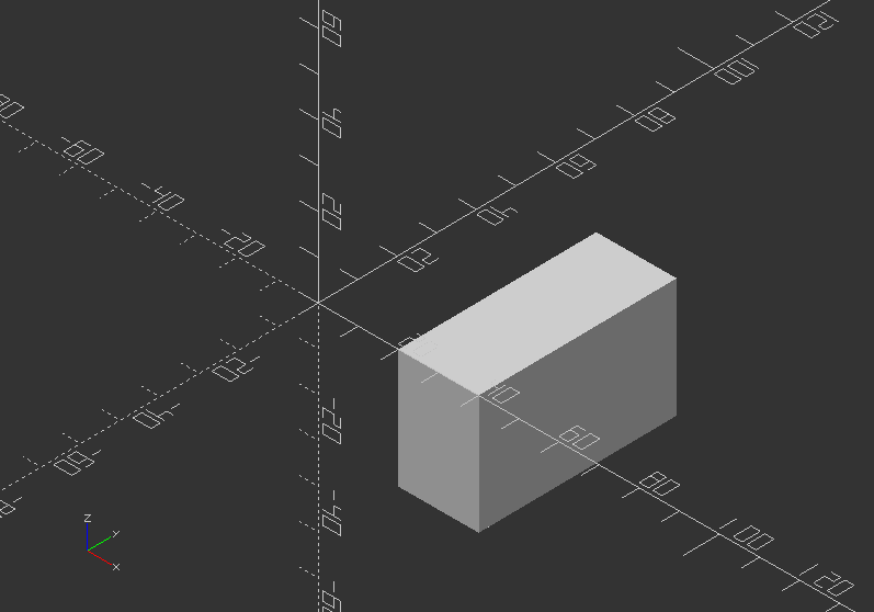
intersection()
- creates a shape from an overlap of 2 objects, or an object group.
intersection() {
sphere(30);
cube(35);
}
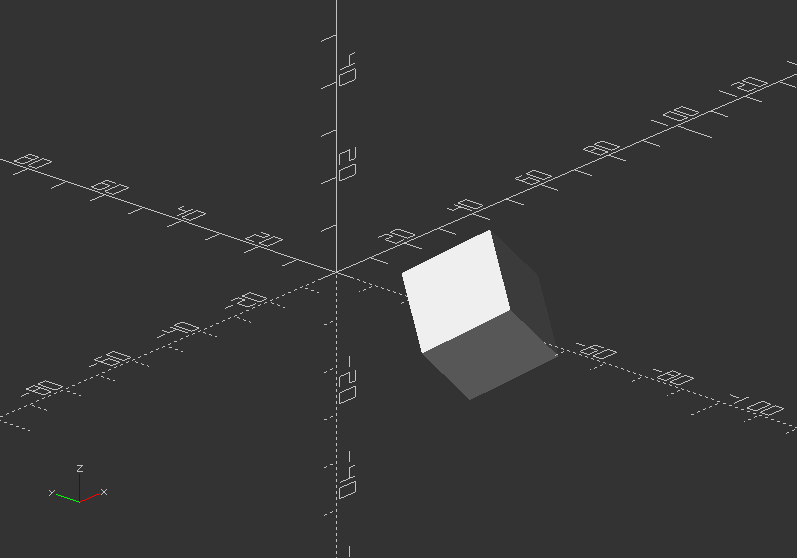
union()
- creates one shape from the outside shape of 2 or more objects (Zooming inside of the object reveals the difference)
union() {
sphere(30);
cube(35);
}
2.4. Transformations
OpenSCAD has different functions for different kind of transformations.
Space-orienting transformations are rotate() for rotation, and translate() for translation.
Shape-altering transformations are scale() for scaling, mirror() for creating mirrored shapes.
Display-altering transformation of shapes is color().
Shape-forming transformations are minkowski(), hull(), and offset().
translate()
- Moves the object or a group of objects along a specific vector
- Arguments are optional.
- Syntax usage: translate(v=[x, y, z]) {...}
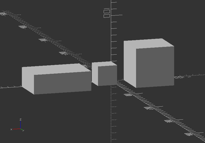
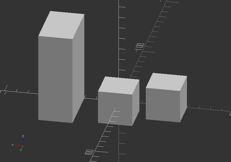
Translate a cube:
cube(20);
translate([20, 0, 0])
cube(10);
translate([30, 0, 0])
cube(5);
rotate()
- Turns the object or a group of objects around one or more axis of the coordinate system or an arbitrary axis.
- Argument names are optional, if you they are in the specified order.
- Syntax usage: rotate(a=deg_a, v=[x, y, z]) {...}
- Argument a can be a vector, thus ignoring Argument v.
- Argument v sets an arbitrary axis about which the object is rotated.
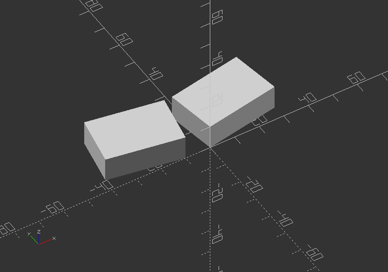
Rotate a box:
rotate(a=[0, 180, 0]) cube([20, 50,30]);
```
```
is the same like below, whereas translate will set the next box beside:
translate([ 40, 0, 0])
rotate(a=180, v=[0, 1, 0]) cube([20, 50, 30]);
Rotate with a single scalar argument rotates around the Z axis, which is useful for 2D objects:
translate([-50, 0, 0])
rotate(45) square(30);
The regular use is rotate([x, y, z]):
translate([-20, -40, 0])
rotate([45, 45, 0]) cube(20);
scale()
- Changes the size of an object using a specified vector.
- The argument name is optional.
- Syntax usage: scale(v=[x, y, z]) {...}
Scale an object:
cube(30); //Default cube
translate([-80, 0, 0]) //Move it aside
scale(2)
cube(30);
translate([50, 0, 0]) //Move it aside
scale([3, 2, 1]) //Scale
cube(30);
mirror()
- Mirrors an object or group of objects on a plane through the origin.
- The argument is a vector, that activates mirroring using 1, while 0 indicates no action.
- Syntax usage: mirror([x, y, z]) {...}
Mirror an object:
rotate([0, 0, 10]) cube([30, 20, 10]);
Try different planes:
mirror([1, 0, 0])
translate([10, 0, 0])
rotate([0, 0, 10])
cube([30, 20, 10]);
!There are more transformations, that I will explain later!
For now, lets carry on with the next chapter!
multmatrix()
- Multiplies the geometry of an object or a group of objects with a given affine transformation matrix.
- One Matrix is 4 x 3 - a vector of 3 row vectors with 4 elements.
- Another Matrix is 4 x 4 - a vector of 4 row vectors, whereas the 4th row is always [0,0,0,1].
-
Syntax usage: multmatrix(m=[...]) {...}
-
Next a breakdown, what you can do with independent elements in the matrix:
| | | | | | --- | --- | --- | --- | | [Scale X] | [Shear X along Y] | [Shear X along Z] | [Translate X] | | [Shear Y along X] | [Scale Y] | [Shear Y along Z] | [Translate Y] | | [Shear Z along X] | [Shear Z along Y] | [Scale Z] | [Translate Z] |
- The fourth row is forced to [0,0,0,1] and is therefore not processed by OpenSCAD
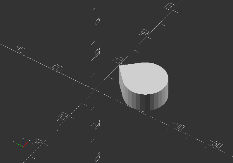
Use a 3x4 multimatrix on an object to create a teardrop:
angle=45;
multmatrix(m=[[cos(angle), -sin(angle), 0, 10],
[sin(angle), cos(angle), 0, -20],
[0, 0, 1, 0],
[0, 0, 0, 1]])
union() {
cylinder(r=10, h=10, center=false);
cube(size=[10, 10, 10],center=false);
}
First build a 4x4 matrix variable, then apply it to multmatrix:
M=[ [1, 0, 0, 0],
[0, 1, 0.7, 30],
[0, 0, 1, 0],
[0, 0, 0, 1]];
Now apply the parameter to a matrix:
multmatrix(M) {
union() {
cylinder(r=10, h=10, center=false);
cube(size=[10, 10, 10],center=false);
}
}

color()
- Displays the object in a specific RGB color + Alpha value
- It is only useful in preview mode F5, as the color will not be transmitted to the rendered object
- Default alpha value is 1.0 (opaque)
- Syntax usage: color([r, g, b, a]) {...}
- r is RED CHANNEL, g is GREEN CHANNEL, b is BLUE CHANNEL
- Each channel holds a value between 0 and 1/[1:255]
- Colors can also be defined by name
Here all color names:
| | | | --- | --- | | Category | Names | | Purples | Lavender, Thistle, Plum, Violet, Orchid, Fuchsia, Magenta, MediumOrchid, MediumPurple, BlueViolet, DarkViolet, DarkOrchid, DarkMagenta, Purple, Indigo, DarkSlateBlue, SlateBlue, MediumSlateBlue | | Pinks | Pink, LightPink, HotPink, DeepPink, MediumVioletRed, PaleVioletRed | | Blues | Aqua, Cyan, LightCyan, PaleTurquoise, Aquamarine, Turquoise, MediumTurquoise, DarkTurquoise, CadetBlue, SteelBlue, LightSteelBlue,PowderBlue,LightBlue, SkyBlue, LightSkyBlue, DeepSkyBlue, DodgerBlue, CornflowerBlue, RoyalBlue, Blue, MediumBlue, DarkBlue, Navy, MidnightBlue | | Reds | IndianRed, LightCoral, Salmon, DarkSalmon, LightSalmon, Red, Crimson, FireBrick, DarkRed | | Greens | GreenYellow, Chartreuse, LawnGreen, Lime, LimeGreen, PaleGreen, LightGreen, MediumSpringGreen, SpringGreen, MediumSeaGreen, SeaGreen, ForestGreen, Green, DarkGreen, YellowGreen, OliveDrab, Olive, DarkOliveGreen, MediumAquamarine, DarkSeaGreen, LightSeaGreen, DarkCyan, Teal | | Oranges | LightSalmon, Coral, Tomato, OrangeRed, DarkOrange, Orange | | Yellows | Gold, Yellow, LightYellow, LemonChiffon, LightGoldenrod, Yellow, PapayaWhip, Moccasin, PeachPuff, PaleGoldenrod, Khaki, DarkKhaki | | Browns | Cornsilk, BlanchedAlmond, Bisque, NavajoWhite, Wheat, BurlyWood, Tan, RosyBrown, SandyBrown, Goldenrod, DarkGoldenrod, Peru, Chocolate, SaddleBrown, Sienna, Brown, Maroon | | Whites | White, Snow, Honeydew, MintCream, Azure, AliceBlue, GhostWhite, WhiteSmoke, Seashell, Beige, OldLace, FloralWhite, Ivory, AntiqueWhite, Linen, LavenderBlush, MistyRose | | Grays | Gainsboro, LightGrey, Silver, DarkGray, Gray, DimGray, LightSlateGray, SlateGray, DarkSlateGray, Black |
A third way is using Hex values, which can be give in 4 formants, #rgb #rgba #rrggbb #rrggbbaa
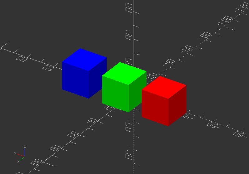
Give objects color:
color("red") translate([-40, 0, 0]) cube(20);
color([0,1,0]) translate([-10, 0, 0]) cube(20);
color("#0000ff") translate([20, 0, 0]) cube(20);
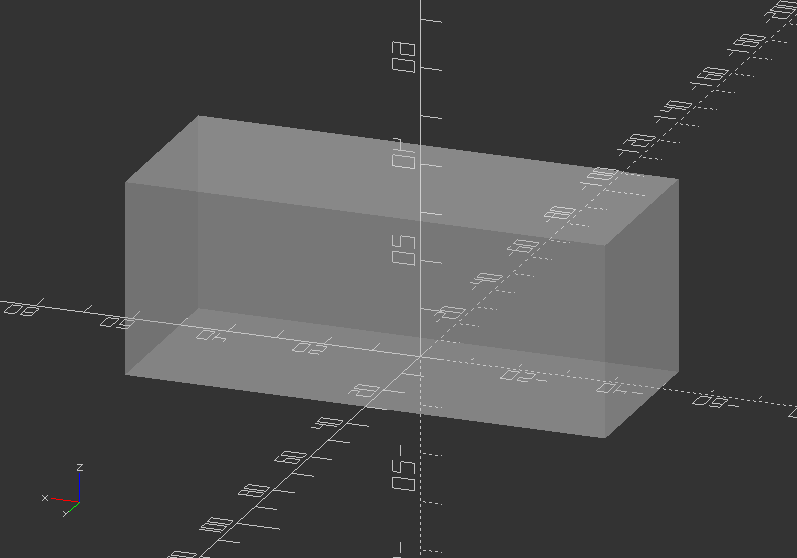
Try to add some alpha:
color([1, 1, 1, 0.3]) translate([-50, -10, 0]) cube([100, 40, 40]);
offset()
- Creates a new 2D interior or exterior outline
- There are 2 modes of operation, radial and offset
- Offset creates an outline with fixed surrounding, while radial behaves like a surrounding circle
- Outlines can be given an optional chamfer
- Offset is useful to make thin walls
- Parameters are:
r>> Amount to offset the polygon. When negative, the polygon is turn inward. It specifies the radius of the circle in radius mode.
delta>> Distance between original and offset polygon line. Negative places it inward. It is used for the offset mode.
chamfer >> Boolean (default: false). Dedicates if edges are cutoff (charmfered).
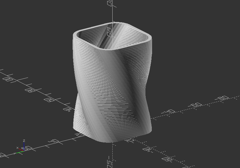
Build a little vase:
linear_extrude(height=60, twist=90, slices=60) {
difference() {
offset(r=10) {
square(20, center=true):
}
offset(r=8) {
square(20, center=true);
}
}
}
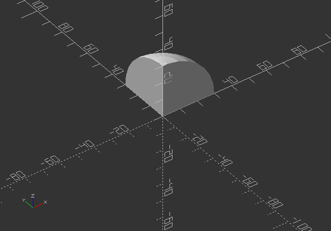
minkowski()
- Displays the minkowski sum of child nodes
- It is useful to create round corners for boxes or flat bodies (spheres or cylinders)
- Minkowski is very computational expensive, so you CPU can go very busy with it
- Syntax usage: minkowski() {...}
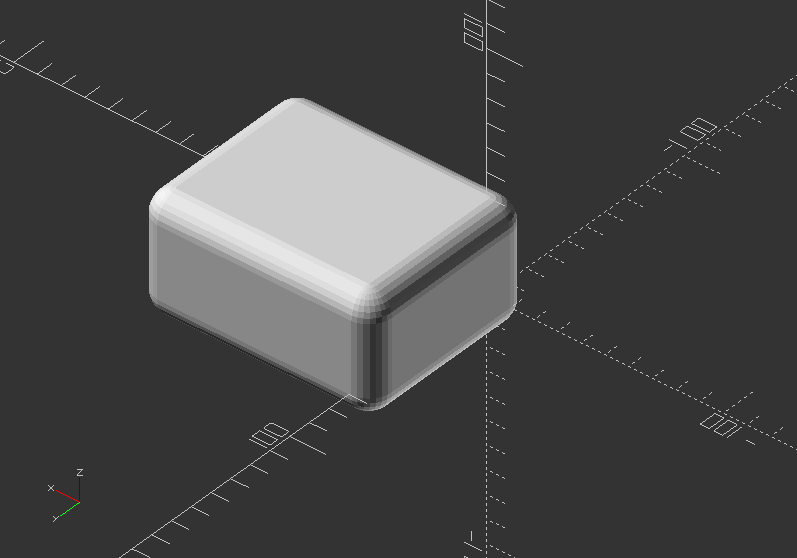
Minkowski example:
minkowski() {
sphere(10);
cube([80, 60, 30]);
}
hull()
- Displays the convex hull of objects
- It can create new shapes by creating a group of objects, that can connected via hull to one mesh
- Syntax usage: hull() {...}
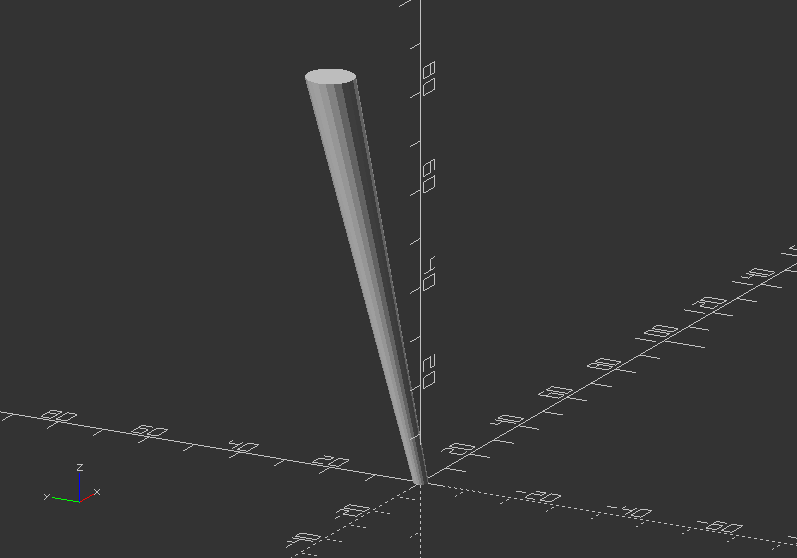
Table leg with hull():
$fn=80;
hull() {
cylinder(h=0.01, d=3, $fn=$fn);
translate([0, 20, 80])
cylinder(h=0.01, d=10, $fn=$fn);
}
Exercise:
Try to create a bottom for the vase, either with hull() or minkowski()!
hull() {
translate([11, 11, 0])
cylinder(h=2, d=16);
translate([-11, 11, 0])
cylinder(h=2, d=16);
translate([11, -11, 0])
cylinder(h=2, d=16);
translate([-11, -11, 0])
cylinder(h=2, d=16);
}
Exercise for minkowski():
minkowski() {
translate([0, 0, 1])
cube([22, 22, 2], center=true);
cylinder(h=2, d=16);
}
2.5. 3D Primitives
There are three basic 3D primitives in OpenSCAD namely cube(), sphere(), and cylinder().
cube()
- Creates a cube at the origin of the coordinate system, but place the cube in its first octane
- The template syntax for cube:
cube(size=x,center=true/false);
or
cube(size=[x,y,z],center=true/false);
- Using center=true will match the cubes origin with the origin of the coordinate system
- To apply different sizes for each plane along an axis, squared brackets are used -> [x,y,z]
- Equivalent code:
cube(size=8);
cube(18);
cube([8, 18, 28]);
size=38;
cube(size);
size=[38, 48, 58];
cube(size);
Try following code below to understand offset() combined with translate()
translate([-60, 0, 0])
cube(30); //cube with squared sizes all around
cube(30, center=true); //squared cube with center in offset 0,0,0 of the coordinate system
translate([30, 0, 0])
cube([30, 50, 80]); //cube with different sizes in x, y, and z
Now try this code version with translate() to position all versions side-by-side!
translate([200, 0, 0])
cube(size=8);
translate([160, 0, 0])
cube(18);
translate([120, 0, 0])
cube([8, 18, 28]);
size1=38;
translate([60, 0, 0])
cube(size1);
size2=[38, 48, 58];
translate([0, 0, 0])
cube(size2);
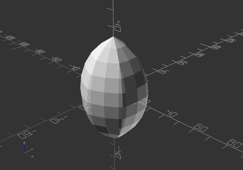
sphere()
- Creates a sphere at the origin of the coordinate system.
- Parameter are:
r>> Radius, while r is not needed to assigned as the decimal automatically is addressed to radius
d >> Diameter of the sphere
$fa >> Fragment angle in degrees
$fs >> Fragment size in mm
$fn >> Resolution of shape through numbers of faces
- Default values of sphere() parameters yields:
sphere(r=10, $fn=0, $fa=12, $fs=1);
radius=5; //parametric value describing radius, change it to 1, 5, 10
$fn=20; //parametric value describing resolution, change it to 4,10, 40, 80
translate([0, 0, radius]) //move it up by radius
sphere(radius, $fn=$fn); //create sphere with assigned radius

Exercise:
- Create 2 variables called radius and $fn, and apply it to a sphere. Then preview the changes!
translate([60, 0, 0])
sphere(10);
translate([30, 0, 0])
sphere(r=20, $fn=3);
translate([0, 0, 0])
sphere(r=10, $fa=50);
translate([-30, 0, 0])
sphere(r=8, $fs=3);
translate([-65, 0, 0])
sphere(r=15, $fn=200);
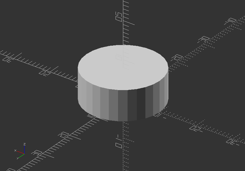
cylinder()
- Creates a cylinder at the origin of the coordinate system, while the pivot of the cylinder is the bottom
- Using center=true will offset the cylinder in the center of the shape, including on the Z axis
- The parameter naming are optional, but need to be used in the correct order
- So it is appropriate to use the parameter names to define cylinder shape
- Parameter:
h >> Height of the cylinder or cone
r >> Radius of cylinder - r1=r2=r
r1 >> Radius bottom of cone
r2 >> Radius, top of cone
d >> Diameter of cylinder - r1=r2=d/2
d1 >> Diameter, bottom of cone - r1=d2/2*
d2 >> Diameter, top of cone - r2=d2/2*
center >> Offset boolean with false as default, true
$fa >> Minimum angle (in degrees) of each fragment
$fs >> Minimum circumferential length of each fragment
$fn >> Fixed number of fragments in 360 degrees
- If you use one parameter name in this list: h, r, r1, r2, d1, d2, you will need to name all further used parameters
- $fa, $fs, $fn always need to be named (universal, not only with cylinder)
- Using cylinder to make holes in a shape need to have a high $fn resolution and slightly bigger, than the wanted size.
cylinder(d=20, h=8);
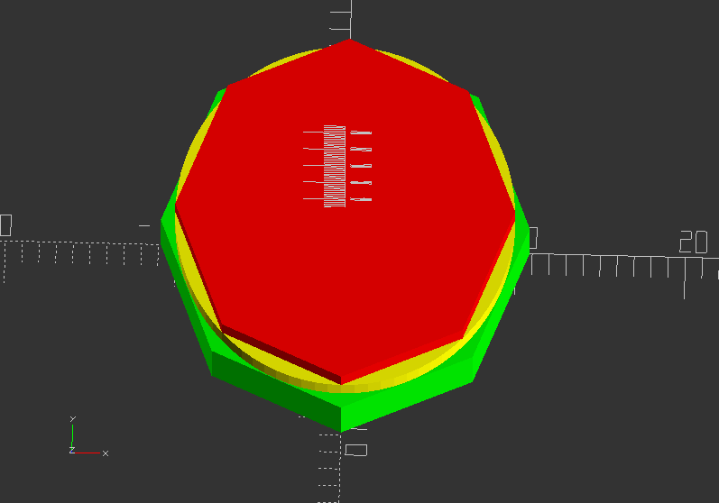
Showcase of circumscribed holes:
color([1, 1, 0])cylinder(h=20, d=20, $fn=80);
color([1, 0, 0]) cylinder(h=25, d=20, $fn=8);
color([0, 1, 0]) cylinder(h=15, d=21.7, $fn=8); //This is a circumscribed hole
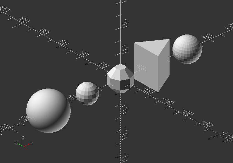
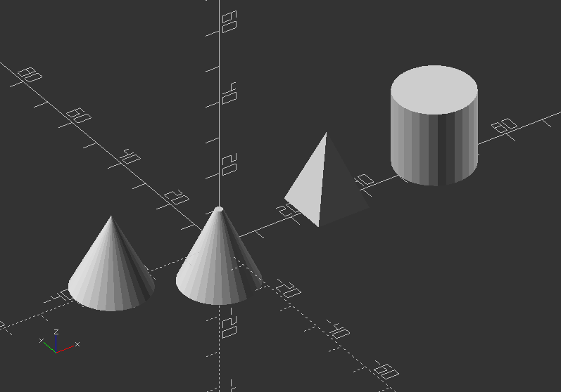
Exercise:
Create a cylinder, a pyramid and a cone!
cylinder(20, 10, center=true); //Not using the parameter names: First number = d, second number = r1, rest remains default (r2=1)
translate([-30, 0, 0])
cylinder(20, r1=10, r2=0); //Using the parameter name r will dedicate the same number to top and bottom
translate([30, 0, 0])
rotate([0, 0, 45])
cylinder(h=20, r1=10, r2=0, $fn=4); //A cylinder using all parameters
translate([60, 0, 0])
cylinder(h=20, d=20); //A cylinder using all parameters
polyhedron()
- is an advanced and therefore most general primitive solid
- it can create any regular or irregular shape including shapes with concave and convex features
- this is only mentioned here to complete the list of 3D solids. We will not use this shape at all.
- There are many ways to do shapes by combining basic shapes (see the code below)
If it is not possible to create a shape in other ways, polyhedron() can achieve it
Polyhedrons contain points and faces >> polyhedron(points[[x,y,z],...],faces=[[p1,p2,p3],...],convexity=N);
You can use different methods in your design to achieve the same results.
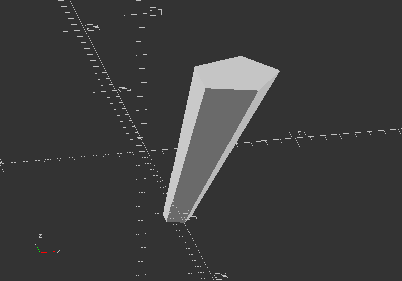
Here an example:
polyhedron(points=[[0, -10, 60], [0, 10, 60], [0, 10, 0], [0, -10 ,0], [60, -10, 60], [60, 10, 60]],
faces=[[0, 3, 2], [0, 2, 1], [3, 0, 4], [1, 2, 5], [0, 5, 4], [0, 1, 5], [5, 2, 4], [4, 2, 3]]);
//Or 2 cubes and intersection
translate([0, -60, 0])
difference() {
rotate([0, 0, -90])
cube([20, 60, 60]);
rotate([-45, 0, -90])
cube([20, 60, 100]);
}
Exercise:
Create a piece of furniture like a table, chair, lamp or something like that!
Use transformations and 3D shapes you just learned!
2.6. 2D Primitives
- 2D primitives can be used to be transformed to 3D objects via extrusion (offset example)
- Although infinitely thin, they are previewed and rendered with 1 mm thickness
- There are 4 different 2D primitives in OpenSCAD: square(), circle(), and polygon()
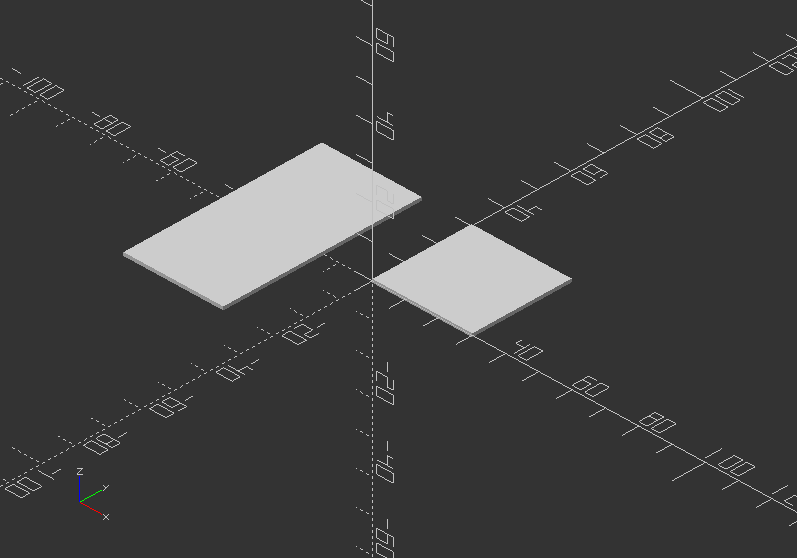
square()
- Creates a square or rectangle in the first quadrant
- When parameter center=true, the square will be placed on the origin
- Syntax usage:
square(size,center);
or
square([size x, size y],center);
or both without center
- Parameters are:
size >> single value for a square, two values in a vector for a rectangle
center >> Boolean (Default: false), will center object in [0,0] of coordinate system if true
Here a basic example:
square(30);
translate([-30, 0, 0])
square([30, 60], center=true);
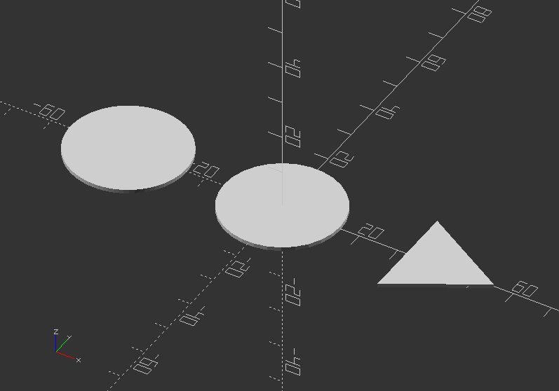
circle()
- Creates a circle around the origin
- All parameters, except r, must be named
- Syntax usage: circle(r=radius|d=diameter);
- Parameters are:
r >> Circle radius, naming is not necessary
d >> Circle diameter
$fa >> Minimum angle of each fragment
$fs >> Minimum circumferential length of each fragment
$fn >> Number of fragments in 360 degrees
A simple example:
circle(15);
translate([-40, 0, 0])
circle(d=30, $fn=80);
translate([40, 0, 0])
circle(d=30, $fn=3); //Experiment with $fn to create more regular polygons
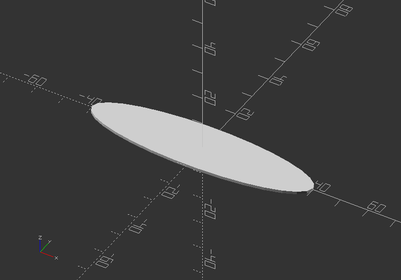
An ellipse can be created with scale() circle();
scale([2, 0.5])
circle(20);
polygon()
- Creates a multiple sided shape from a list of x,y coordinates
- This is the most powerful 2D object, including shapes with convex and concave edges.
- It is also possible to place holes within the shape.
- Syntax usage: polygon(points=[[x,y],...],paths=[[p1,p2,p3..],...], convexity = N);
- Parameters are:
points >> A list of x,y points of the polygon (Points are indexed from 0 to n-1)
paths >> All points are used in order listed
single vector >> Order to traverse the points. May in different order with all or part
multiple vectors >> Creates primary and secondary shapes (like difference). Secondary shapes may be wholly and partially within primary shape
convexity >> Integer number of "inward" curves, i.e. expected path crosses through polygon
Here an example:
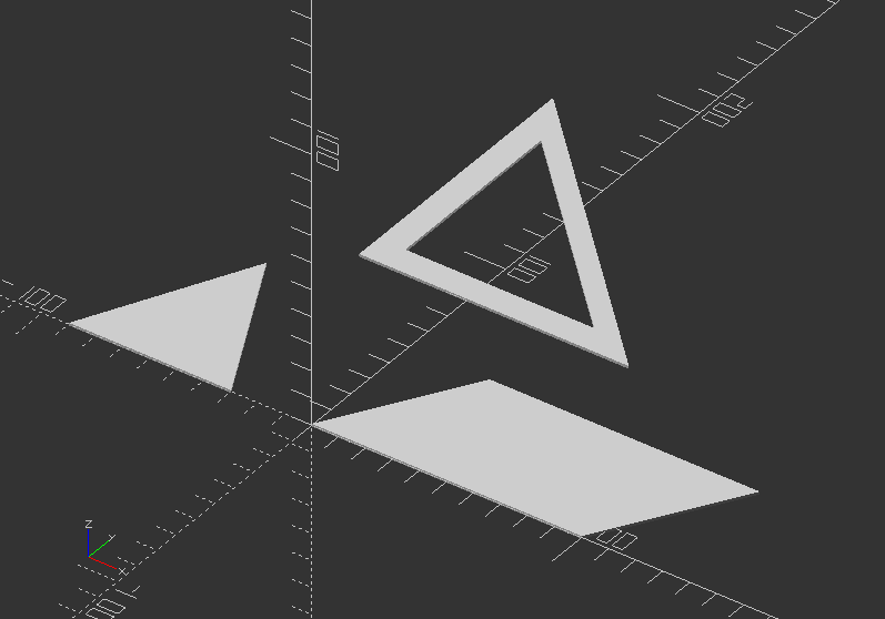
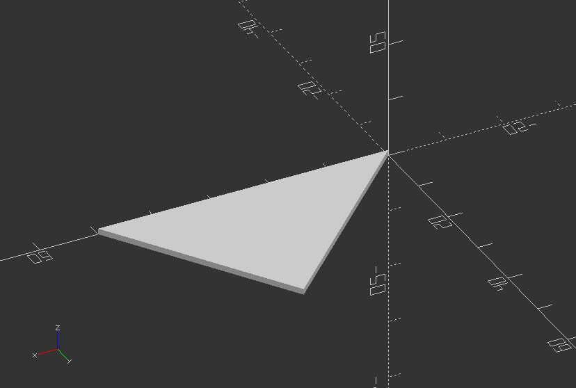
polygon(points=[[0, 0], [100, 0], [130, 50], [30, 50]]);
translate([-60, 0, 0])
polygon([[-30, 0], [0, 60], [30, 0]]);
translate([-40, 80, 0])
polygon(points=[[0, 0], [100, 0], [0, 100], [10, 10], [80, 10], [10, 80]], paths=[[0, 1, 2], [3,4,5]], convexity=10);
2.7. Text
- Creates text as a 2D geometric object.
- It uses fonts installed on the local system or a provided as separate font file
- Syntax usage: text(string);
- Parameters are:
text >> The text to generate (String)
size >> It determine height over baseline (Decimal - default: 10)
font >> It is not the name of the font file, but the logical name: Help -> Font List (String)
halign >> Horizontal alignment for the text "left" "center" "right" (String - default: "left")
valign >> Vertical alignment for text "top" "center" "baseline" "bottom" (String - default: baseline)
spacing >> Decrease/increase character spacing, the greater the further apart (Decimal - default: 1)
direction >> Direction of text flow "ltr" (left-to-right), "rtl", "ttb", "btt" (String - default: "ltr")
language >> Language of the text (String - default: en)
script >> Script of language (String - default: "latin")
$fn >> Subdivision of curved path segments provided by freetype
- Use linear_extrude(size_z) text(string) to create 3D text.
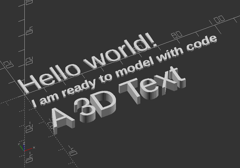
Text: Experiment with text parameters:
text("Hello world!");
translate([0, -10, 0])
text("I am ready to model with code", size=5,font="Liberation Sans:style=Bold Italic");
translate([0, -30, 0])
linear_extrude(5)
text("A 3D Text", size=12, font="Liberation Sans");
2.8. Extrusion
linear_extrude()
- A process of creating an object with fixed cross-sectional profile
- There are 2 commands to create 3D shapes from a 2D shape: linear_extrude()
- This operation takes a 2D object as input and generates a 3D object as a result
- The shape of x and y will be projected upwards along the z axis.
- If you use transformations to change the object, then its transformed version will be extruded.
- Syntax usage: linear_extrude(height, center, convexity, twist, slices, scale, $fn) {...}
- Parameters are:
height >> z value for resulting 3D object >> It must be positive
twist >> Number of degrees, that the shape will twist throughout its extrusion. Positive value twists clockwise, negative value turns around anti-clockwise
center >> If center is true, the extruded object will be centered in the z axis of origin
slices >> Number of intermediate points along the Z-axis of the extrusion. Its Default increases with twist value
scale >> Scales the 2d shape to this value over the height of the extrusion (scalar or vector)
$fn >> Increases resolution resulting in higher smoothness
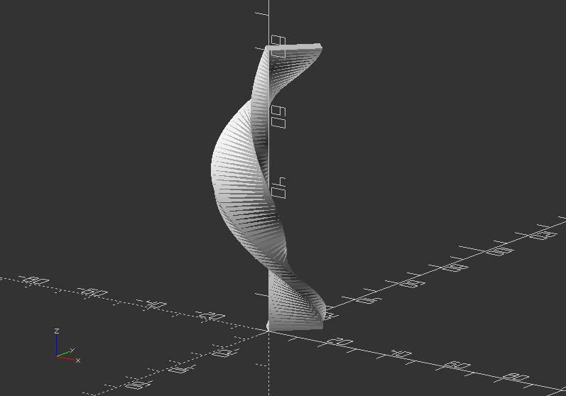
Linear extrusion 1:
linear_extrude(80, twist=360, slices=80) {
rotate(45)
scale([1.5, 0.5])
square(10);
}
Linear extrusion 2:
linear_extrude(height=10, center=true, convexity=10, scale=3)
translate([2, 0, 0])
circle(r=1);
rotate_extrude()
- Like using a potter wheel, rotational extrusion spins a 2D shape around the Z-axis
- It has rotational symmetry
- The 2D shape must lie entirely on the left or right side of the Y-axis in order to work
- Syntax Usage: rotate_extrude(angle,convexity) {...}
- Parameters are:
angle >> Specifies number of degrees to sweep, starting at positive x (Integer - default: 360). Negative angle sweeps clockwise
convexity >> If the extrusion fails for a non-trivial 2D shape, try a value like 10 (recommended)
$fa >> Minimum angle of each fragment
$fs >> Minimum circumferential length of each fragment
$fn >> Fixed number of fragments in 360 degrees
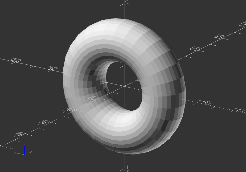
Rotational extrusion 1 - Create a Donut:
rotate([0, 90, 0])
rotate_extrude(convexity=10)
translate([22, 0, 0]) //Change the y number
circle(r=10);
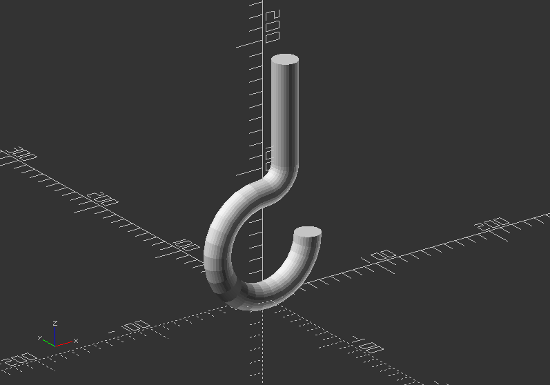
Rotational extrusion 2 - Create a hook:
translate([0, 0, 100])
rotate([-90, 0, 0])
union() {
translate([0, 60, 0])
rotate_extrude(angle=270, convexity=10)
translate([40, 0])
circle(10);
rotate_extrude(angle=90, convexity=10)
translate([20, 0]) circle(10);
translate([20, 0, 0])
rotate([90, 0, 0])
cylinder(h=80, r=10);
}
Extruding a polygon:
rotate_extrude($fn=200) polygon(points=[[0, 0], [15, 0], [20, 5], [20, 20], [10, 25], [12, 50], [0, 50]]);
Change the code to make a real vase design out of it!
Solution:
rotate_extrude($fn=200) polygon(points=[[0, 0], [15, 0], [20, 5], [20, 20], [10, 25], [12, 50], [10, 50], [5, 5]]);
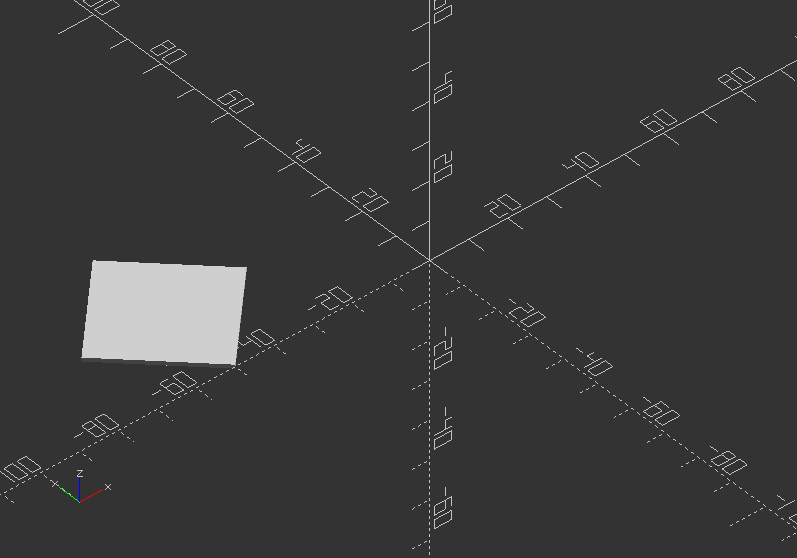
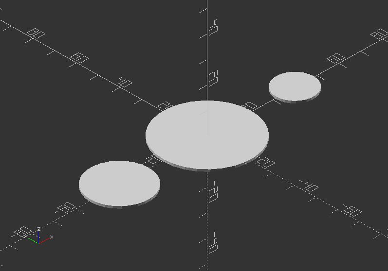
2.9. Projection
projection()
- Creates a 2D drawing from a 3D model
- It is projecting a 3D object to the x,y plane with z=0
- The parameter:
cut >> If cut=true, only the points with z=0 are considered for the 2D shape. If cut=false, points above and below are considered as well.
- To do a particular cutout, the parameter needs to be true >> translate and rotate it in position.
- Is necessary to export objects in DXF Format or SVG Format.
Example:
projection(cut=true) translate([-40, 0, 15]) sphere(20);
projection(cut=false) sphere(20);
projection(cut=true) translate([40, 0, 18]) sphere(20);
Without projection:
With projection:
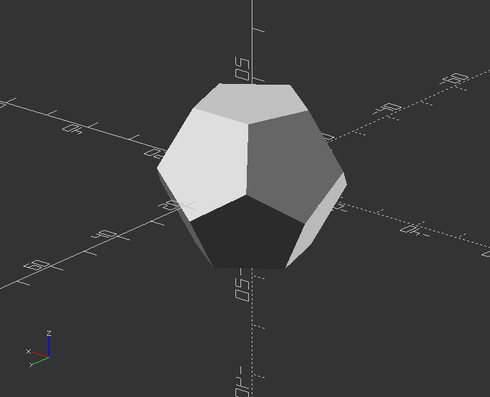
3.1. 3D Shapes
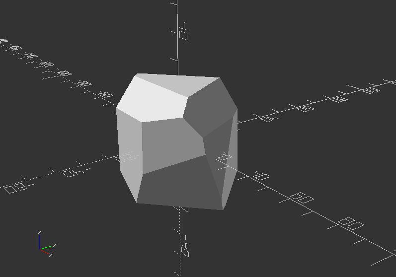
Dodecahedron by intersection 6 boxes
module dodecahedron(height) {
scale([height, height, height]) { //Scale by height parameter
intersection() {
cube([2, 2, 1], center=true); //Make a cube
intersection_for(i=[0:4]) { //Loop i from 0 to 4, and intersect results
rotate([0, 0, 72*i]) //Rotate object below 72*i degrees around Z axis
rotate([116.565, 0, 0]) //Rotate object below 116.565 degree around X axis
cube([2, 2, 1], center=true);
}
}
}
}
Now create a Dodecahedron:
dodecahedron(30);
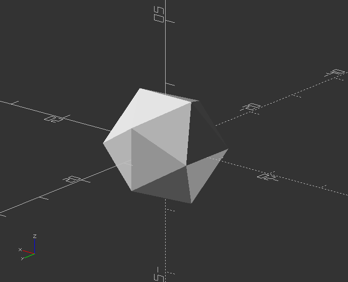
Icosahedron by intersection of 3 golden-ratio rectangles
module icosahedron(size) {
phi=0.5*(sqrt(5)+1); //The Golden Ratio
st=size/10000; //Microscopic sheet thickness
hull() {
cube([size*phi, size,st], true); //First rectangle
rotate([90, 90, 0]) cube([size*phi, size, st], true); //Second rectangle
rotate([90, 0, 90]) cube([size*phi, size, st], true); //Third rectangle
}
}
Now create a Icosahedron from the module:
size=10;
icosahedron(size);
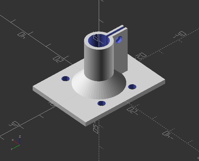
Create a shaft bracket
fn = 60; //Circle resolution
eps = 0.03; //Small number
slop = 0.2; //Printer slop: shrinkage of ID of a hole
//Basic values of bracket platform
bp_width = 30; //Bracket platform width
bp_length = 40; //Bracket platform length
bp_thickness = 2; //Bracket platform thickness
screw_size = 3.0 + slop; //Diameter of mounting screw hole
//Basic values of shaft
shaft_diameter = 8.0+slop; //Shaft diameter
shaft_thickness = 1.5; //Shaft collar thickness
//Basic values of bracket clamp
bc_area = 2; //Thickness of bracket clamp area
bc_length = 20; //Length of bracket clamp area
bc_width = screw_size*2.8; //Clamping block width
bc_height = bc_length; //Clamping block height
bc_thickness = 3; //Clamping block thickness
//Basic values of bracket clamp
notch_width = 1; //Width of notch in bracket clamp
notch_length = 15; //Bracket notch length
bf_height = 5; //Bracket angled flange height
//Other variables
bcol = shaft_diameter+2*shaft_thickness; //Bracket collar OD
shaft_length = bc_length + eps*2; //Shaft length for cutout
//Module that creates bracket
module bracket() {
difference() {
union() {
translate([-bp_width/2, -bp_length/2, 0]) cube([bp_width, bp_length, bp_thickness]); //Flat platform-top
translate([0, 0, -bc_length]) cylinder(r = bcol/2, h=bc_length, $fn=fn); //Outer round clamp
rotate([180, 0, 0]) cylinder(r1=(bp_width+bcol)/4, r2=bcol/2, h=bf_height, $fn=fn); //Flange
translate([-bc_thickness/2, shaft_diameter/2, -bc_length]) cube([bc_thickness, bc_width, bc_height]); //Shaft clamp block
}
translate([bp_width/2 - 1.5*screw_size, bp_length/2 - 1.5*shaft_diameter, -(eps)])
cylinder(r=screw_size/2, h=bp_thickness+2*eps, $fn=12); //Mounting hole
translate([bp_width/2 - 1.5*screw_size, -bp_length/2 + 1.5*shaft_diameter, -(eps)])
cylinder(r=screw_size/2, h=bp_thickness+2*eps, $fn=12); //Mounting hole
translate([-bp_width/2 + 1.5*screw_size, bp_length/2 - 1.5*shaft_diameter, -(eps)])
cylinder(r=screw_size/2, h=bp_thickness+2*eps, $fn=12); //Mounting hole
translate([-bp_width/2 + 1.5*screw_size, -bp_length/2 + 1.5*shaft_diameter, -(eps)])
cylinder(r=screw_size/2, h=bp_thickness+2*eps, $fn=12); //Mounting hole
//translate([-notch_width/2, -(bcol+eps)/2, -(bc_area+eps)]) //Notch both sides
translate([-notch_width/2, 0, -(bc_length+eps)]) //Notch one side only
cube([notch_width, bcol+bc_height+2*eps, notch_length]); //Notch cutout in cylinder
translate([0, 0, eps-shaft_length]) cylinder(r = shaft_diameter/2, h=shaft_length, $fn=fn); //Hole for shaft
translate([-bc_width/2, bcol/2 + screw_size, -bc_length+screw_size])
rotate([0, 90, 0]) cylinder(r=screw_size/2, h=bc_width+2*eps, $fn=12); //Hole in shaft clamp block
//translate([0, 0,-25]) color("red") cube([50, 50, 50]); //DEBUG cutaway
}
}
Rotated bracket call:
rotate([180, 0, 0]) bracket();
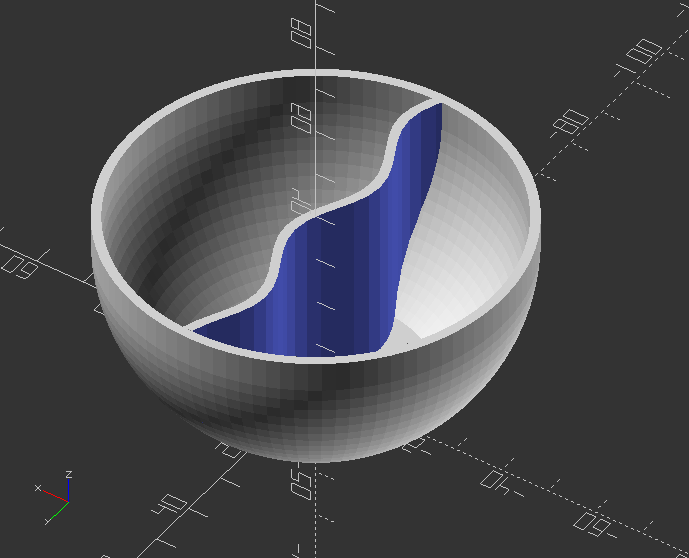
Create a simple bowl
//Initiate basic variables with values
resolution=20;
diameter=80;
depth=40;
middle_wall=true; //for cerial that doesnt get soggy
flat_bottom=5;
wall_thickness=2;
middle_resolution=3;
middle_wave=10;
$fn = resolution;
//Create module for bowl
module bowl() {
hull() {
translate([0, 0, diameter/2-flat_bottom]) sphere(d=diameter);
translate([0, 0, depth]) sphere(d=diameter);
}
}
//Negative form to make bowl hollow
module taken_bowl() {
intersection() {
scale([(diameter/(diameter+(wall_thickness*2))), (diameter/(diameter+(wall_thickness*2))), 1]) bowl();
translate([0, 0, wall_thickness]) cylinder(d=diameter, h=depth);
}
}
//Make the bowl hollow
intersection() {
difference() {
bowl();
taken_bowl();
}
cylinder(d=diameter, h=depth);
}
//If true, add a separation wall
if(middle_wall == true) {
intersection() {
taken_bowl();
middle_sine(depth);
}
}
//Separation wall in bowl
module middle_sine(depth) {
r = 0;
h = 0;
w = depth;
// amplitude
s = 3;
step = middle_resolution;
// cycles
c= middle_wave;
// small number
e=0.02;
module sinwave(w) {
for(a=[0:step:diameter-step]) {
hull() {
translate([r-w, a, -2*s])
cube([2*w, e, 2*s+s*sin(c*a)]);
translate([r-w,a+step, -2*s])
cube([2*w, e, 2*s+s*sin(c*(a+step))]);
}
}
}
translate([0, -diameter/2, 0])
rotate([0, 90, 0])
difference() {
sinwave(w);
translate([0, 0, -wall_thickness]) sinwave(w=w*2);
}
}
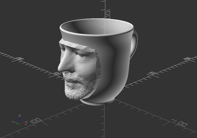
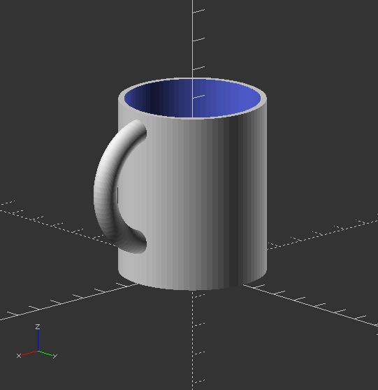
Create simple mug
//Basic variables with assigned values
diameter=50;
height=60;
wall_thickness=2;
handle_thickness=8;
front_icon="";
front_icon_size=30;
icon_depth=5;
bottom_icon="";
icon_size=25;
resolution=10;
bottom_thickness=5;
hand_size=20;
handle=true;
handle_height=-2;
handle_resolution=5;
$fn= resolution;
//Module for positive shape of mug
module mug_added(diameter, height, hand_size, height, handle_thickness, handle_height, handle_resolution) {
cylinder(d=diameter, h=height);
if(handle == true) {
handle(hand_size, height, handle_thickness, handle_height, handle_resolution);
}
}
//Module for negative cutout of mug inside
module mug_taken(diameter, height, wall_thickness, bottom_thickness) {
translate([0, 0, bottom_thickness]) cylinder(d=diameter-(wall_thickness*2), h=height);
}
//Module for mug handle
module handle(hand_size, height, handle_thickness, handle_height, handle_resolution) {
$fn = handle_resolution;
translate([hand_size, 0, (height-hand_size-(handle_thickness/2)+handle_height)])
rotate([90, 0, 0])
rotate_extrude() {
translate([hand_size, 0, 0]) circle(d=handle_thickness);
}
}
//Module to assemble mug with no text
module mug_no_text(diameter, height, hand_size, height, handle_thickness, handle_height, handle_resolution) {
difference() {
mug_added(diameter, height, hand_size, height, handle_thickness, handle_height, handle_resolution);
mug_taken(diameter, height, wall_thickness, bottom_thickness);
}
}
Create mug:
difference() {
mug_no_text(diameter, height, hand_size, height, handle_thickness, handle_height, handle_resolution);
scale([-1, 1, 1])
translate([0, -diameter/2+icon_depth/2, height/2])
rotate([90, 0, 0])
linear_extrude(height=bottom_thickness/2) {
text(text=bottom_icon, font="fontawesome", size=icon_size, halign="center", valign="center");
}
}
intersection() {
difference() {
translate([0, 0, height/2])
rotate([90, 0, 0])
linear_extrude(height = diameter) {
text(text=front_icon, font="fontawesome", size=front_icon_size, halign="center", valign="center");
}
mug_taken(diameter, height, wall_thickness, bottom_thickness);
}
mug_added(diameter=diameter+icon_depth, height, hand_size, height, hasndle_thickness, handle_height, handle_resolution);
}
3.2. 2D Shapes
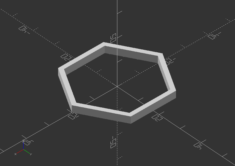
Create an extruded ngon ring shapes
height=3; //Height of z extrusion
outerSize=20; //Outer diameter
innerSize=18; //Inner diameter
corners=6;
module ngonRing(innerSize, outerSize, height, corners) {
linear_extrude(height)
difference() {
circle(outerSize, $fn=corners);
circle(innerSize, $fn=corners);
}
}
ngonRing(innerSize, outerSize, height, corners);
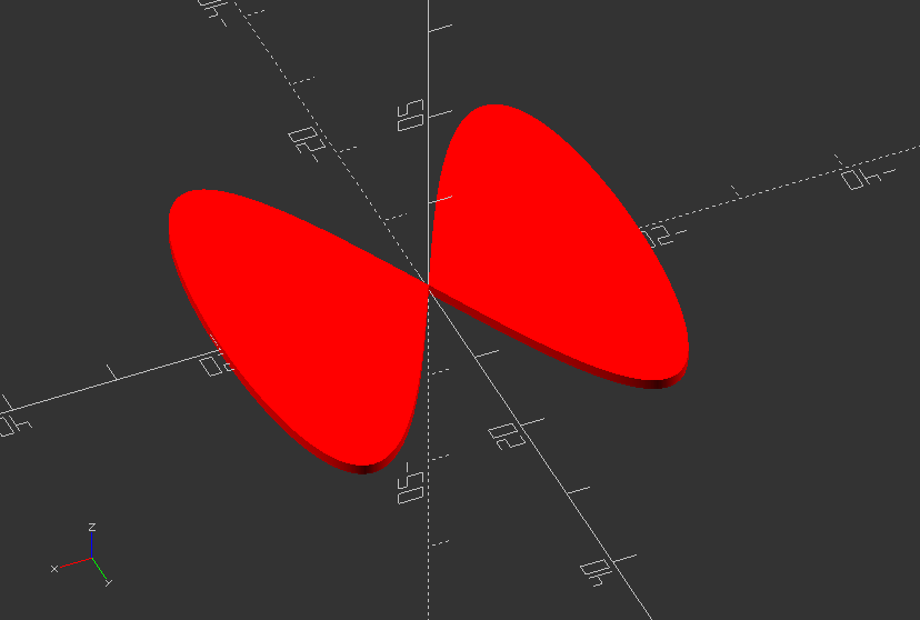
Create a complex round shape
function circle(radius) = [for(phi=[0:1:720])[radius*cos(phi/2), radius*sin(phi)]];
color("red") polygon(circle(20));
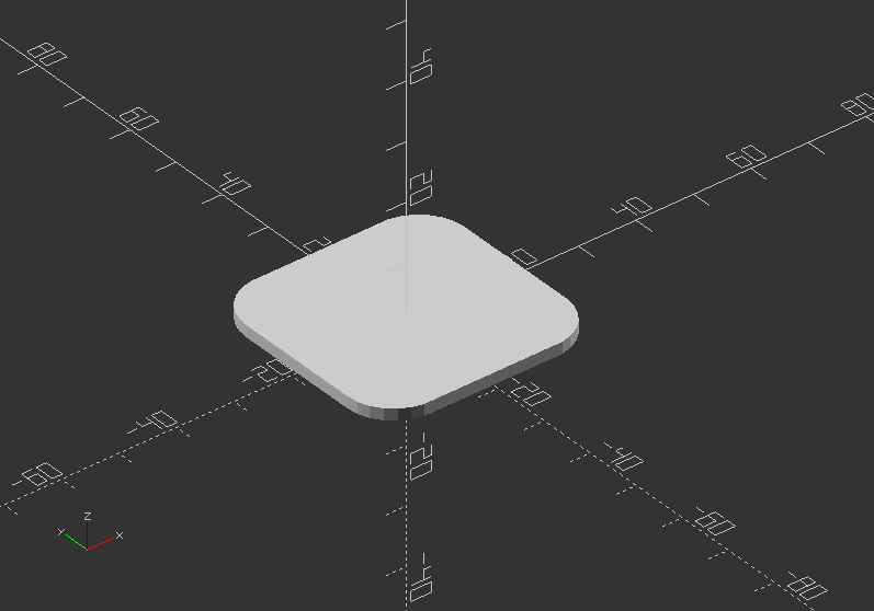
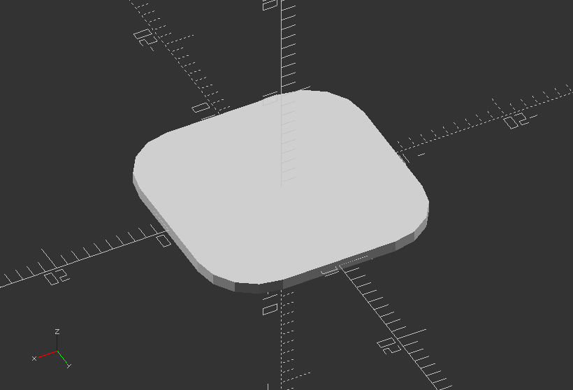
Create a rounded square
size=[20, 20]; //Dedicated by x and y position
radius=5; //Dedicated smoothness of rounded edge
module roundedSquare(size, r=radius) {
minkowski() {
square([size[0]-radius*2, size[1]-radius*2], center=true);
circle(r=radius);
}
}
roundedSquare(size, r=radius);
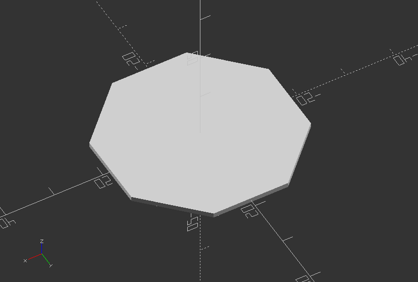
Create a ngon, a 2D shape with variable of n sides and a customized radius
sides = 8;
radius = 20;
// The orientation might change with the implementation of circle...
module ngon(sides, radius, center=false){
rotate([0, 0, 360/sides/2]) circle(r=radius, $fn=sides);
}
ngon(sides, radius, center=false);
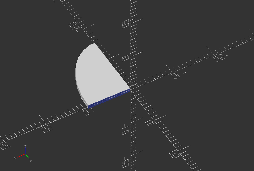
Create an ellipse, that can be quartered
width=20; //Size in x
height=30; //Size in y
numQuarters=1; //1-4 for each quarter
module ellipse(width, height) {
scale([1, height/width, 1]) circle(r=width/2);
}
module ellipsePart(width,height,numQuarters) {
o = 1; //slight overlap to fix a bug
difference() {
ellipse(width,height);
if(numQuarters <= 3)
translate([0-width/2-o, 0-height/2-o, 0]) square([width/2+o, height/2+o]);
if(numQuarters <= 2)
translate([0-width/2-o, -o, 0]) square([width/2+o, height/2+o*2]);
if(numQuarters < 2)
translate([-o, 0, 0]) square([width/2+o*2, height/2+o]);
}
}
ellipsePart(width, height, numQuarters);
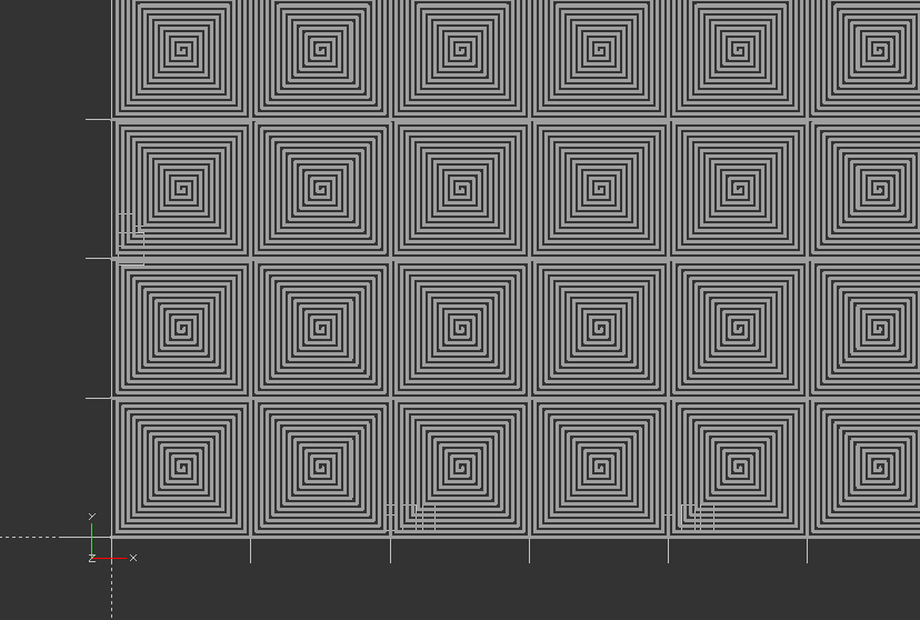
Create a turtle spiral shape
function turtle(x, y, angle) = [[x, y], angle];
//The forward function results in moving the turtle over distance where the new x and y position of the turtle are calculated of the turtle (turtle[1]) remains the same
function forward(turtle, length) = turtle(turtle[0][0] + length * cos(turtle[1]), turtle[0][1] + length * sin(turtle[1]), turtle[1]);
//The turn function results in a new orientation of the turtle where angle is added to the old orientation to determine the new orientation. The position of the turtle remains the same.
function turn(turtle, angle) = [turtle[0], turtle[1] + angle];
//The move_the_turtle module recursive moves along a path that is determined by length, angle and lines length and angle may change in the recursive module lines determines the number of lines drawn by the turtle.
module move_the_turtle(turtle, length, angle, lines, line_width){
if ( lines > 0 ) {
new_turtle_forwarded = forward(turtle,length);
line(turtle[0],new_turtle_forwarded[0],line_width);
new_turtle_turned = turn(new_turtle_forwarded,angle);
move_the_turtle(new_turtle_turned, length-2, angle, lines-1, line_width);
}
}
Create a turtle t using the modules above with start in the origin with angle 0 degrees:
t1 = turtle(0, 0, 0);
linear_extrude(height=2.5)
for (i=[0:7]) {
for (j=[0:7]) {
translate([length*i, length*j, 0]) move_the_turtle(t1,length, 90, 50, line_width);
}
}
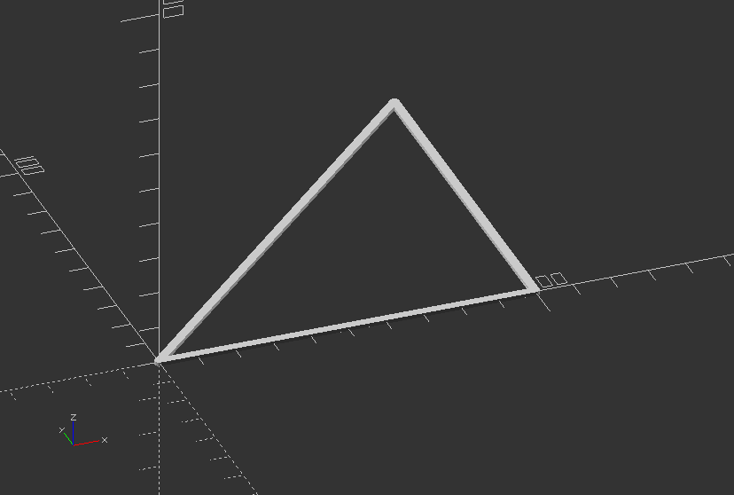
Create a triangle with the modules above:
t2 = forward(t1, length);
line(t1[0], t2[0], line_width);
t3 = forward(turn(t2, 90), length);
line(t2[0], t3[0], line_width);
t4 = forward(turn(t3,135), sqrt(2)*length);
line(t3[0], t4[0], line_width);
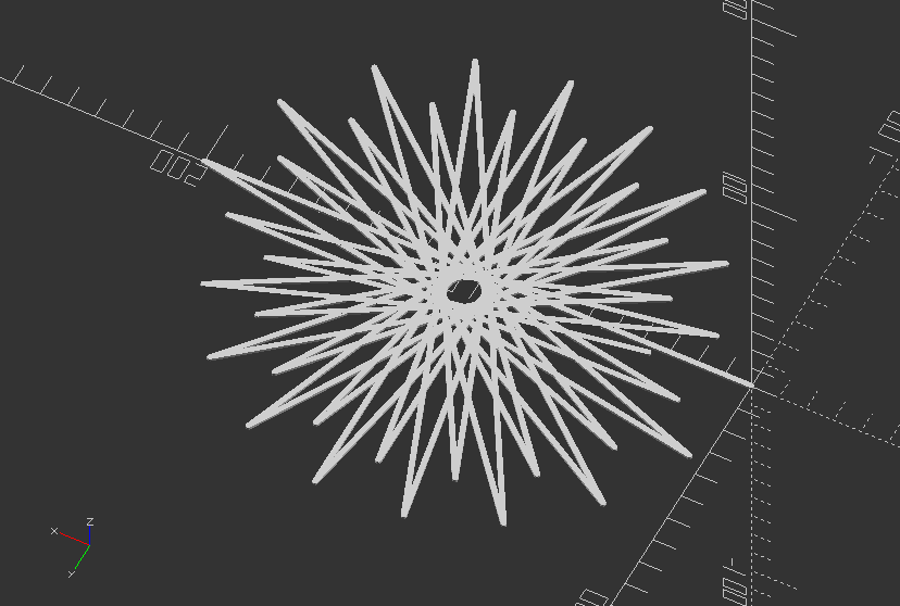
Create a turtle start with the modules above:
move_the_turtle(t1, 200, 170, 36, 1);
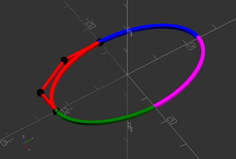
Polyline: Demonstration of symmetrical poly (cubic) beziers
//The four black dots are the control points of the red bezier. The complete control the shape of the figure. The four beziers are connected with each other though their end points.
$fn=50;
//Intersection points on the x- and y-axis determine the position of the end points on these axis. Change these values to model the curve.
x_intersection = -14;
y_intersection = -24;
//The points of bezier1 are brought on the straight line to ensure that all curves are tangent.
bezier1=[[0,y_intersection],[-8,y_intersection],[x_intersection,-12],[x_intersection,0]];
//w determines the width of the line (thickness of the surface)
w = 0.5; //[0.5:3]
//deltat determines the stepsize of the 'running variable' t.
//The smaller the step the smoother the curve
deltat = 0.05;
//Cubic bezier function
function cubic_bezier(points) = [for (t=[0:deltat:1+deltat]) pow(1-t,3)*points[0]+3*pow((1-t),2)*t*points[1]+3*(1-t)*pow(t,2)*points[2]+pow(t,3)*points[3]];
//Module of the polyline
module line(p1, p2, w) {
hull() {
translate(p1) circle(r=w, $fn=20);
translate(p2) circle(r=w, $fn=20);
}
}
//Using the, slightly modified, polyline module from JustinSDK (thanks Justin Lin). See his documentation here: https://openhome.cc/eGossip/OpenSCAD/Polyline.html. It's good reading.
module polyline(points, index, w) {
if(index < len(points)) {
line(points[index - 1], points[index], w);
polyline(points, index + 1, w);
}
}
//This module make the help-lines and the control points visible
module control_points(bezier1) {
color("red") polyline(bezier1, 1, w/1.5);
for (i=[0:len(bezier1)-1] ) {
color("black") translate(bezier1[i]) circle(r=1);
}
}
//Create four beziers just by using the mirror function of OpenSCAD all beziers are given a
//different color to separate them.
control_points(bezier1);
//Use hull to make a closed shape
//hull(){
union() {
color("red") polyline(cubic_bezier(bezier1),1,w);
color("blue") mirror([0, 1, 0]) polyline(cubic_bezier(bezier1), 1, w);
color("green") mirror([1, 0, 0]) polyline(cubic_bezier(bezier1), 1, w);
color("magenta") mirror([0, 1, 0]) mirror([1, 0, 0]) polyline(cubic_bezier(bezier1), 1, w);
}
//}
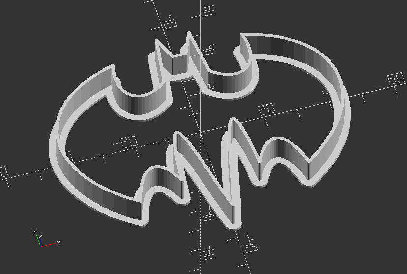
Polyline: Create a Batman cookie cutter
//Increase the default surface resolution
$fn=50;
//Creates lists of points used as line and control points for bezier curves
poly1 = [[0, 22], [2, 22], [5, 29], [7, 14]];
bezier1 = [poly1[3], [15, 7], [23, 12], [20, 24]];
bezier2 = [bezier1[3], [50, 16], [50, -10], [26, -26]];
bezier3 = [bezier2[3], [23, -14], [17, -11], [12, -22]];
bezier4 = [bezier3[3], [9, 16], [5, -18], [0, -35]];
//w determines the width of the line (thickness of the surface)
w = 0.5; //[0.5:3]
//deltat determines the stepsize of the 'running variable' t. The smaller the step the smoother the curve
deltat = 0.05;
function cubic_bezier(points) = [for (t=[0:deltat:1+deltat]) pow(1-t,3)*points[0]+3*pow((1-t),2)*t*points[1]+3*(1-t)*pow(t,2)*points[2]+pow(t,3)*points[3]];
//Module that creates a line from
module line(p1, p2, w) {
hull() {
translate(p1) circle(r=w, $fn=20);
translate(p2) circle(r=w, $fn=20);
}
}
//This module make the help-lines and the control points visible
module control_points(bezier1) {
color("red") polyline(bezier1, 1, w/1.5);
for (i=[0:len(bezier1)-1] ) {
color("black") translate(bezier1[i]) circle(r=1);
}
}
/*Using the, slightly modified, poyline module from JustinSDK (thanks Justin Lin). See his documentation here: https://openhome.cc/eGossip/OpenSCAD/Polyline.html. It's good read. */
module polyline(points, index, w) {
if(index < len(points)) {
line(points[index - 1], points[index], w);
polyline(points, index+1, w);
}
}
//Module that creates one half of the shape
module half_bat() {
polyline(poly1, 1, w);
color("red") polyline(cubic_bezier(bezier1), 1, w);
color("blue") polyline(cubic_bezier(bezier2), 1, w);
color("magenta") polyline(cubic_bezier(bezier3), 1, w);
color("green") polyline(cubic_bezier(bezier4), 1, w);
}
//Module that mirrors the half into a full shape
module bat_logo() {
half_bat();
mirror([1, 0, 0]) half_bat();
}
//Uncomment to visualize all control points of bezier curve
//control_points(bezier1);
//control_points(bezier2);
//control_points(bezier3);
//control_points(bezier4);
//Create the cutter out of 2 shapes
union() {
//Create on bat logo with extruded 1 mm thickness and an offset width of 2
translate([0, 0, 0])
linear_extrude(1)
offset(2)
bat_logo();
//Extrude another bat logo with 1 mm width and 10 mm height/thickness
linear_extrude(10)
bat_logo();
}
3.3. Text
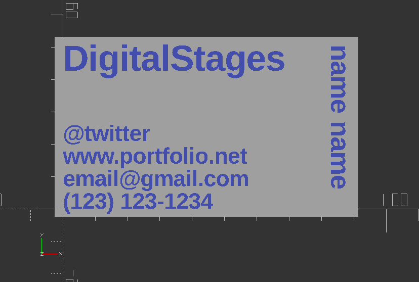
Build a Business card
//This is the size of a normal card, but padding will be added to the sides and height if set
card_width = 88.9;
card_height = 50.8;
card_thickness = .5;
padding_sides = 5;
padding_height = 5;
//Font and fonts thickness
text_thickness = 1;
font = "Liberation Sans:style=Bold";
//Text for name
name = "name name";
name_text_size = 6;
name_taken = "true";
//Text for contact details
twitter = "@twitter";
website = "www.portfolio.net";
email = "email@gmail.com";
phone = "(123) 123-1234";
contact_font_size= 5;
contact_info_taken = "true";
//Order of info
order_twitter = 3;
order_google = 2;
order_email = 1;
order_phone = 0;
spacing = 2;
//Text for company name
company_name = "DigitalStages";
company_name_font_size = 8;
company_name_taken = "true";
//Module for base of card
module base() {
translate([-padding_sides/2, -padding_height/2, 0]) cube([card_width+padding_sides, card_height+padding_height, card_thickness]);
}
//Module for Company name
module company() {
translate([0, card_height-company_name_font_size, text_thickness/2]) {
linear_extrude(text_thickness) text(company_name, font=font , size=company_name_font_size);
}
}
//Module for Name
module name() {
translate([card_width-name_text_size, card_height, text_thickness/2]) {
linear_extrude(text_thickness) rotate([0, 0, -90]) text(name, font=font , size=name_text_size);
}
}
//Module for Twitter Details
module twitter() {
translate([0, order_twitter*contact_font_size+(spacing*order_twitter), text_thickness/2]) {
linear_extrude(text_thickness) text(twitter, font=font , size=contact_font_size);
}
}
//Module for Website
module website() {
translate([0, order_google*contact_font_size+(spacing*order_google), text_thickness/2]) {
linear_extrude(text_thickness) text(website, font=font , size=contact_font_size);
}
}
//Module for Email
module email() {
translate([0, order_email*contact_font_size+(spacing*order_email), text_thickness/2]) {
linear_extrude(text_thickness) text(email, font=font , size=contact_font_size);
}
}
//Phone
module phone() {
translate([0, order_phone*contact_font_size+(spacing*order_phone), text_thickness/2]) {
linear_extrude(text_thickness) text(phone, font=font , size=contact_font_size);
}
}
//Module for Contact block
module contact_info() {
twitter();
website();
email();
phone();
}
difference() {
base();
translate([0,0,-card_thickness]) union() {
contact_info();
company();
name();
}
}
//company name taken
if (company_name_taken=="false") {
translate([0, 0, -card_thickness]) company();
}
//contact info taken
if (name_taken=="false") {
translate([0, 0, -card_thickness]) name();
}
//name taken
if (contact_info_taken=="false") {
translate([0, 0, -card_thickness]) contact_info();
}
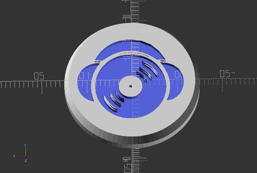
Use icon font to create a nice buttons for your jacket
Keep in mind, you need to install the font DJ Icons on your system first, or use Font Importer script in files!
font="DJ Icons";
string="k";
size=20;
cutIn=1;
transX=0;
transY=0;
union() {
difference() {
//Create basic button
union() {
translate([0,0,2])
cylinder(h=2,d=30,$fn=80);
cylinder(h=2,d1=28,d2=30,$fn=80);
}
//Use text with icon font an cutout extruded text graphic with difference
translate([transX,transY,-1])
linear_extrude(cutIn+1)
text(string,font=font,size=size,halign="center",valign="center");
}
//Create stitch hole
translate([0,0,5])
rotate([0,90,0])
difference() {
cylinder(h=4,d=5,center=true,$fn=20);
cylinder(h=5,d=2.5,center=true,$fn=20);
}
}
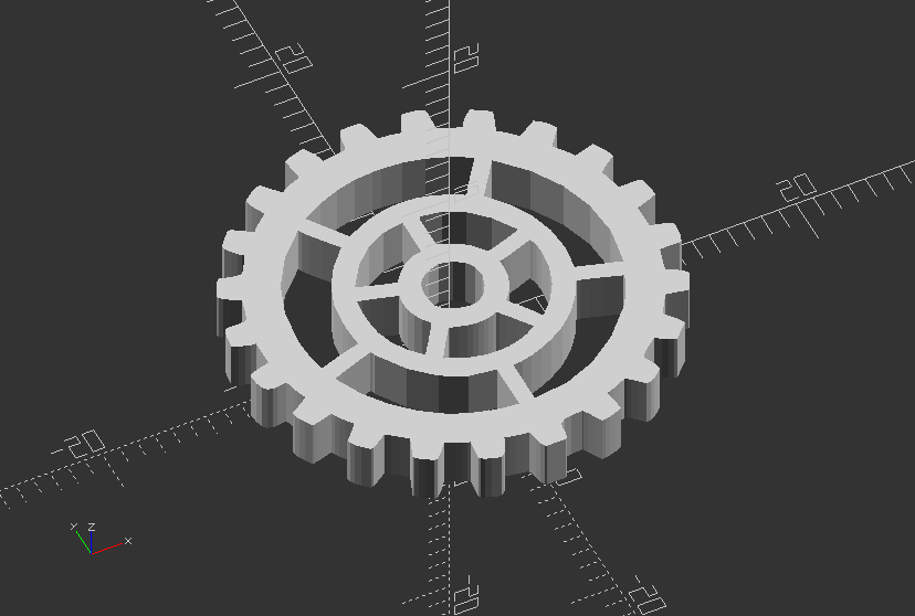
Use icon font to create a gear elements
Keep in mind, you need to install the font Gear Icons on your system first, or use Font Importer script in files!*
font="Gears Icons";
string="n";
size=25;
height=3;
linear_extrude(height)
text(string, font=font, size=size, halign="center", valign="center");
3.4. Transformation
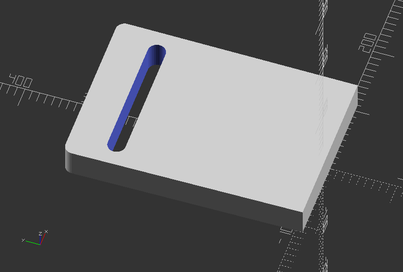
Use hull to create a simple slot
//Simple slot with hull
difference() {
hull() {
translate([100, 0, 20])
cube([20, 20, 40], center=true);
translate([-100, 0, 20])
cube([20, 20, 40], center=true);
translate([100, 300, 20])
cylinder(h=40, r=12, center=true);
translate([-100, 300, 20])
cylinder(h=40, r=12, center=true);
}
hull() {
translate([80, 250, 20])
cylinder(h=40, r=12, center=true);
translate([-80, 250, 20])
cylinder(h=40,r=12, center=true);
}
}
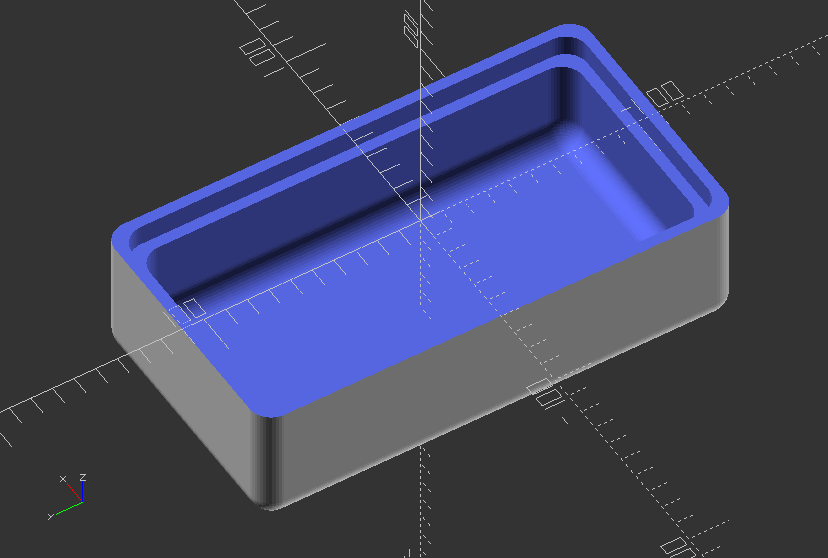
Use minkowski to create an enclosure
$fn=50;
difference() {
minkowski() {
cube([100,200,100], center=true);
sphere(10);
}
//Chop off the top
translate([0,0,50]) cube([130,230,100], center=true);
//Hollow inside
minkowski() {
cube([80,180,80], center=true);
sphere(10);
}
translate([0,0,-10]) {
linear_extrude(100) {
minkowski() {
square([90,190], center=true);
circle(10);
}
}
}
}
3.5. Extrusion
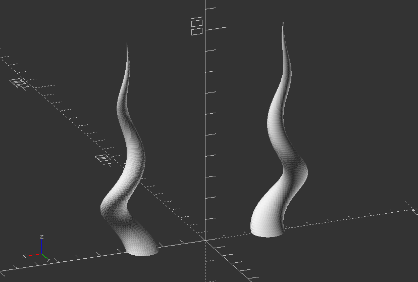
Create twisted horns
//Create horns out ouf a twisted translated circle
module horn(height=100,radius=30,twist=720,$fn=50) {
radius=radius/4;
translate([-radius, 0]) //Translate only in 2D
linear_extrude(height=height, twist=twist, scale=0, $fn=$fn)
translate([radius, 0]) //Translate only in 2D
circle(r=radius);
}
//Now create 2 horn, while one is mirrored, thus creating symmetrical pair
translate([30, 0])
mirror([1, 0, 0])
horn();
translate([-30, 0])
horn();
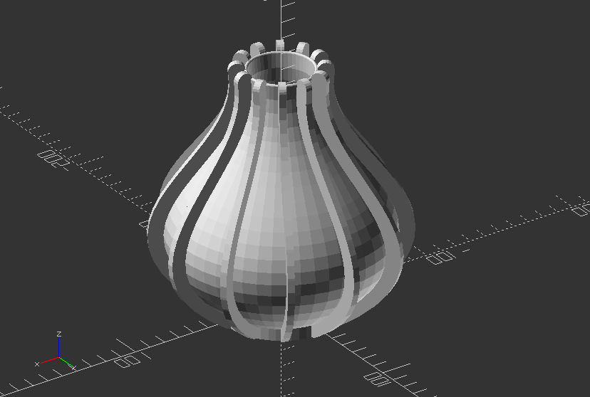
Create vase through rotational extrusion
//radius determines the size of the base of the vase
radius = 30;
//three points (p0, p1, p2) needed to create the quadratic Bezier curve
//four points (p0, p1, p2, p3) needed to create the cubic Bezier curve
p0 = [radius,0];
//as an exercise increment the y value of p1 (e.g in steps of 3)
p1 = [120,60];
p2 = [10,90];
p3 = [20,150];
//w determines the width of the line (thickness of the surface)
w = 5; //[0.5:3]
//deltat determines the stepsize of the 'running variable' t. The smaller the step the smoother the curve
deltat = 0.05;
//Create function for bezier curves
function bezier(p0, p1, p2) = [for (t=[0:deltat:1+deltat]) pow(1-t, 2)*p0+2*(1-t)*t*p1+pow(t, 2)*p2];
function cubic_bezier(p0, p1, p2, p3) = [for (t=[0:deltat:1+deltat]) pow(1-t, 3)*p0+3*pow((1-t), 2)*t*p1+3*(1-t)*pow(t, 2)*p2+pow(t, 3)*p3];
//Create module for polyline
module line(p1, p2, w) {
hull() {
translate(p1) circle(r=w, $fn=20);
translate(p2) circle(r=w, $fn=20);
}
}
/*using the, slightly modified, polyline module from JustinSDK (thanks Justin Lin). See his documentation here: https://openhome.cc/eGossip/OpenSCAD/Polyline.html. It's good reading. */
module polyline(points, index, w) {
if(index < len(points)) {
line(points[index - 1], points[index], w);
polyline(points, index + 1, w);
}
}
//Now create the actual profile shape
for (i=[1:30:360]) {
rotate([0, 0, i])
rotate([90, 0, 0])
linear_extrude(4)
translate([w, 0, 0])
polyline(cubic_bezier(p0, p1, p2, p3), 1, w);
}
//uncomment lines below to create a vase
translate([0, 0, -5]) cylinder(r=radius+w, h=9, $fn=50);
rotate_extrude($fn=50)
//polyline(bezier(p0, p1, p2), 1, w);
polyline(cubic_bezier(p0, p1, p2, p3), 1, 1);
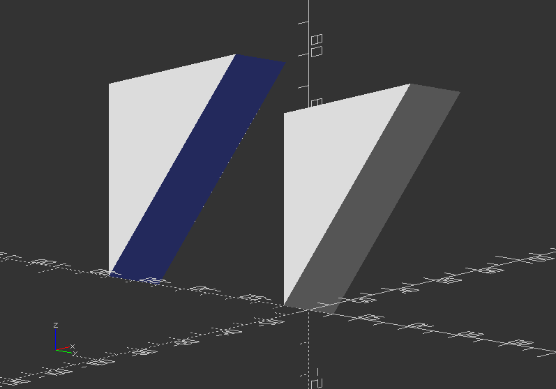
Create a simple triangular prism
module triangle_prism(b, d, h, ht, sc) {
linear_extrude(height=ht, scale=sc)
polygon(points=[[0, 0], [b, 0], [d, h]]);
}
triangle_prism(50, 30, 30, 1, 1);
3.6. Modules
Object Modules
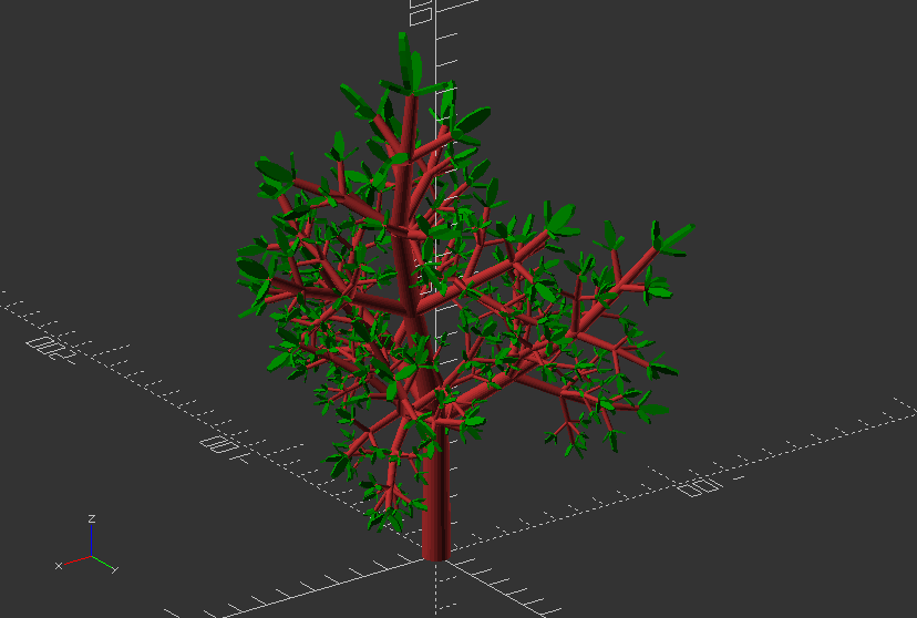
Recursive Module: Create a simple tree
module simple_tree(size, dna, n) {
if (n > 0) {
// trunk
color("brown")
cylinder(r1=size/10, r2=size/12, h=size, $fn=24);
// branches
translate([0, 0, size])
for(bd = dna) {
angx = bd[0];
angz = bd[1];
scal = bd[2];
rotate([angx, 0, angz])
simple_tree(scal*size, dna, n-1);
}
}
else // leaves
color("green")
scale([1, 1, 3])
translate([0, 0, size/6])
rotate([90, 0, 0])
cylinder(r=size/6, h=size/10);
}
// dna is a list of branching data bd of the tree:
//bd[0] - inclination of the branch
//bd[1] - Z rotation angle of the branch
//bd[2] - relative scale of the branch
dna = [ [12, 80, 0.85], [55,0, 0.6], [62, 125, 0.6], [57, -125, 0.6] ];
Module call:
simple_tree(50, dna, 5);
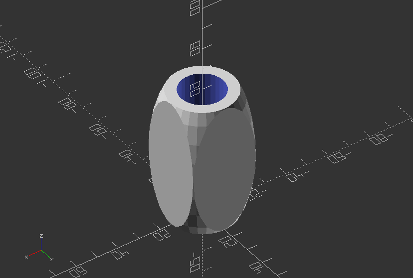
Object Module: Create a little mug
module mug(width, height, bottom_thickness=2, wall_thickness=5) {
r_of_inside=width/2-wall_thickness;
difference() {
translate([0, 0, height/2])
intersection() {
cube([width, width, height], center=true);
scale([1, 1, height/width])
sphere(width/2 * sqrt(2));
}
translate([0,0,bottom_thickness])
cylinder(r=r_of_inside, h=height+0.1);
}
}
Call the mug module:
mug(30, 60);
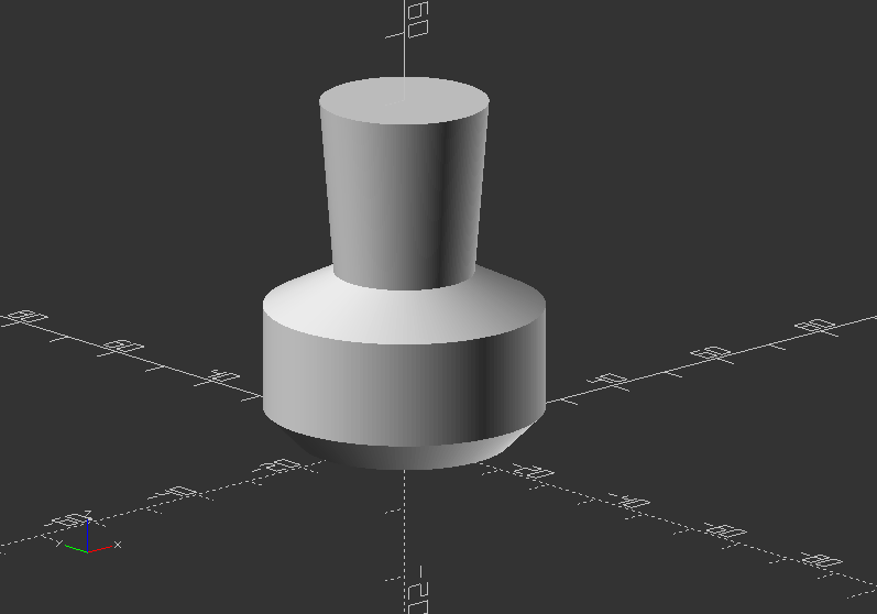
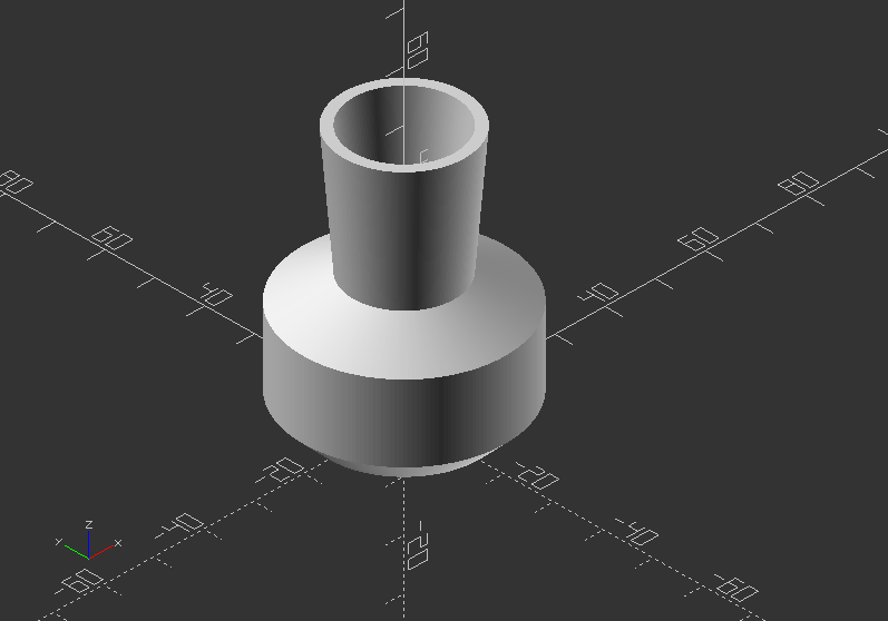
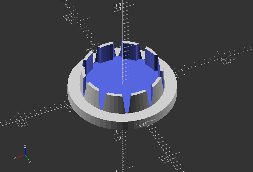
Object Module: Create a compression cover
//outer dia of rod to create cap ID
rod_od = 20.0;
//thickness of cap in mm (each side)
rod_id = 15.6;
//height of cap in mm
cap_high = 2.0;
//tapper of opening in mm
cap_tapper = 0.3;
//cuts in lip for compression
cuts = 10.0;
main_module();
module main_module() { //create module
difference() {
union() { //start union
//create base cap
translate ([0,0,0])
rotate ([0,0,0])
cylinder(cap_high, (rod_od)/2, (rod_od)/2, $fn=60, true);
//create tappered plug
translate ([0, 0, (cap_high*1.5)]) rotate ([0, 0, 0]) cylinder(cap_high*2, (rod_id)/2, (rod_id-(cap_tapper*2))/2, $fn=60, true);
} //end union
//start subtraction of difference
// create opening for compression
translate ([0,0,(cap_high*1.5)+0.1 ]) rotate ([0,0,0]) cylinder(cap_high*2,(rod_id-(cap_tapper*6))/2, (rod_id-(cap_tapper*6))/2, $fn=60, true);
//create pattern for compression lip
for (i=[0360/cuts):360]) {
//theta is degrees set by for loop from 0 to 360 (degrees)
theta=i;
//this sets the x axis point based on the COS of the theta
x = 0+((rod_id/2)-((cap_tapper*3)))*cos(theta);
//this sets the y axis point based on the sin of the theta
y = 0+((rod_id/2)-((cap_tapper*3)))*sin(theta);
//this creates the circle or other object at the x,y point
translate([x, y, ((cap_high*1.5) +.1)]) cylinder(cap_high*2, (cap_tapper*6)/2, (cap_tapper*6)/2, $fn=60, true);
}//end for loop for circle creation
} //end difference
}//end module
Object Module: Create keyholes for screws
module keyhole_mount(thickness, screw_size=3, head_size=6) {
union() {
//Keyhole cutout
translate([0, 0, -0.1])
{
linear_extrude(thickness) {
hull() {
//circle(screw_size/2, $fn=25);
//translate([head_size, 0]) circle(screw_size/2, $fn=25);
}
translate([head_size, 0]) circle(head_size/2, $fn=25);
}
}
//Detent
translate([0, 0, thickness/2])
{
linear_extrude(thickness) {
hull() {
circle(head_size/2+head_size/8, $fn=25);
translate([head_size, 0]) circle(head_size/2+head_size/8, $fn=25);
}
translate([head_size, 0]) circle(head_size/2, $fn=25);
}
}
}
}
//Now implement the keyhole_mount into a board
difference() {
cube([50, 200, 2]);
translate([15, 20, 0]) keyhole_mount(2);
translate([15, 180, 0]) keyhole_mount(2);
}
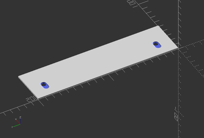
Operational Modules
Operational Module: Linear array in one direction >> x: 0, y: 1, z: 2
module linear_array(axis, count, distance) {
if(axis==0) {
for(i=[0:1:count-1]) {
translate([distance*i,0,0])
children();
}
}
if(axis==1) {
for(i=[0:1:count-1]) {
translate([0,distance*i,0])
children();
}
}
if(axis==2) {
for(i=[0:1:count-1]) {
translate([0,0,distance*i])
children();
}
}
}
//Move some spheres into z - axis
linear_array(2, 5, 40) sphere(20);
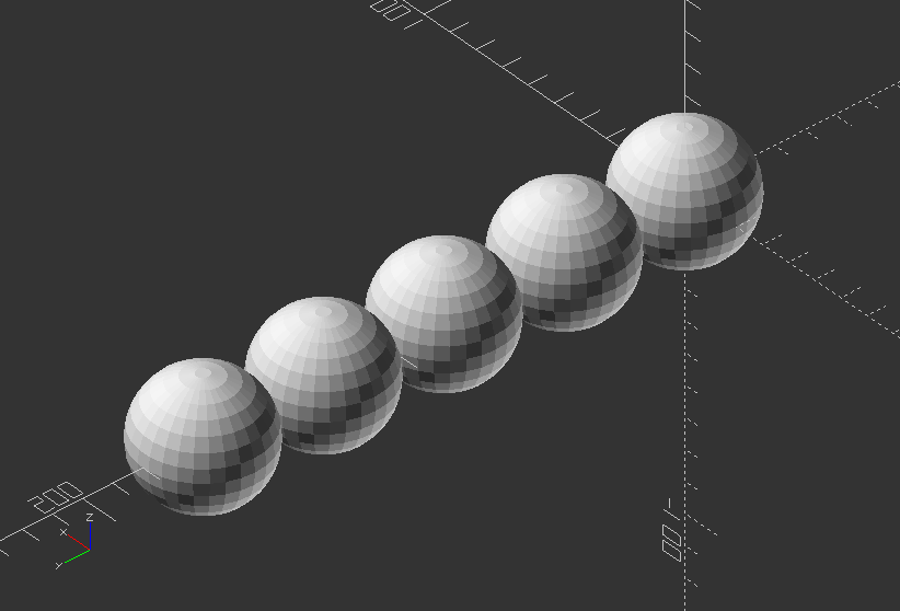
Operational Module: Linear array n all 3 dimensions, use 1 on one axis to make it rectangular
module cubic_array(x, y, z, distance_x, distance_y, distance_z) {
for(i=[0:1:x-1]) {
for(j=[0:1:y-1]) {
for(k=[0:1:z-1]) {
translate([distance_x*i, distance_y*j, distance_z*k])
children();
}
}
}
}
//Implement a cube of cubes
cubic_array(10, 10, 10, 20, 20, 20) cube(17);
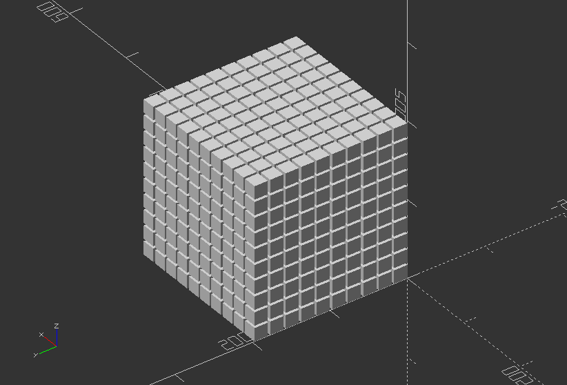
Operational Module: Rotational array that uses center=true/false to change the tilt of each object around the circle
//Use axis to set the axis of circulation >> x: 0, y: 1, z: 2 - whereas z axis has a bug to be solved
module polar_array(radius, count, axis) {
for(i=[0:360/count:360]) {
if(axis==0) {
rotate([i, 0, 0])
translate([0, radius, 0])
children();
}
if(axis==1) {
rotate([0, i, 0])
translate([radius, 0, 0])
children();
}
if(axis==2) {
rotate([90, 0, i])
translate([ 0, 0, radius])
children();
}
}
}
//Revolve it!
polar_array(80, 20, 0) cylinder(h=20, r=10, center=true, $fn=30);
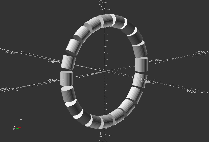
3.7. Loops
Wave model 1 >> Creating wavy design with cubes by using a function
cube_size=2;
h_div=20;
step=0.1;
to=15;
//Function that takes x and y steps in and get step for z out
function f(p, q) = (p * p + q * q) / h_div;
//Loop through each cube and position it according to the resulting x, y, z values
scale(4)
for(a=[-1:step:1], b=[-1:step:1]) {
x=a*to;
y=b*to;
translate([x,y,f(x,y)])
cube(cube_size, center=true);
}
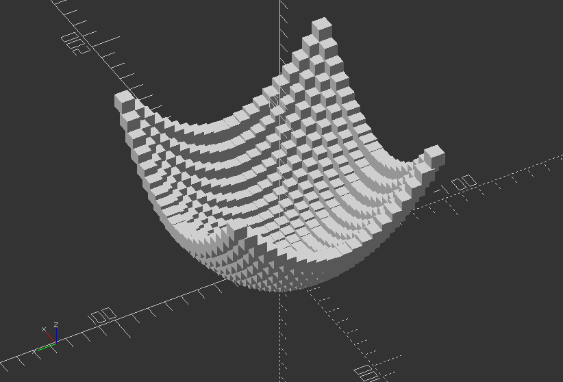
Wave model 2 >> Creating wavy design with cubes by using a function
h_div=30;
step=0.1;
to=15;
//Function that takes x and y steps in and get step for z out
function f(p,q) = (p * p + q * q) / h_div;
//Loop through each cube and position it according to the resulting x,y,z values
scale(4)
for(a=[-1:step:1], b=[-1:step:1]) {
//Create x and y values via for() loop index
x = a * to;
y = b * to;
//x plus step
xps = (a + step) * to;
//y plus step
yps = (b + step) * to;
//Create a lower triangle from the cubes via hull transformation
hull() {
//now create a cube and move it to the resulting position
//(x, y)
translate([x, y, f(x, y)])
cube(size=step, center=true);
//(x, y + step)
translate([x, yps, f(x, yps)])
cube(size=step, center=true);
//(x+step,y)
translate([xps, y, f(xps, y)])
cube(size=step, center=true);
}
//Create the upper triangle from the cubes via hull transformation
hull() {
//now create a cube and move it to the resulting position
//(x, y)
translate([xps, yps, f(xps, yps)])
cube(size=step, center=true);
//(x, y + step)
translate([x, yps, f(x, yps)])
cube(size=step, center=true);
//(x + step, y)
translate([xps, y, f(xps, y)])
cube(size=step, center=true);
}
}
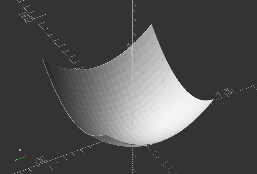
Loops: Create a slot with drill holes
width=20;
length=100;
height=2;
hole_size=5;
hole_dist=18;
module holeySlot(width, height, length, hole_size, hole_dist) {
difference() {
hull() {
for(i=[-length/2, length/2])
translate([i, 0, 0]) cylinder(d=width, h=height);
}
for(j=[-length/2+width/4:hole_dist:length/2-width/4])
translate([j,0,0]) cylinder(d=hole_size, h=20);
}
}
holeySlot(width, height, length, hole_size, hole_dist);
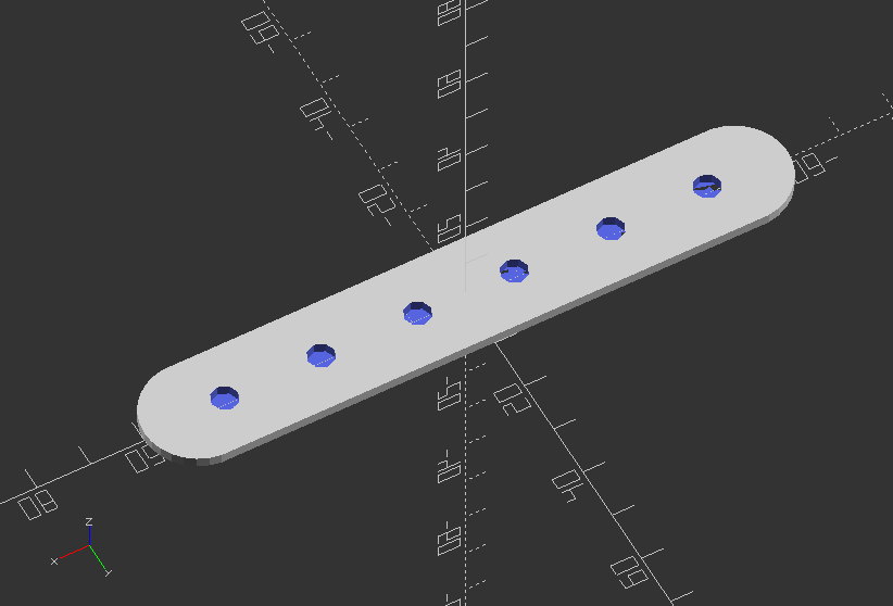
3.8. Math
Math: Create mathematical knots
//Random point
p0 = [-4, 0, 50];
p1 = [2, 7, 4];
p2 = [6, 12, 8];
p3 = [8, 24, 26];
p4 = [10, 12, -12];
//Create a vector list from random points
points = [p0, p1, p2, p3, p4];
//Radius of the knot
w = 18;
//Well it's pi (or at least an approximation, what can I say.
pi = 3.1418;
//Constant to convert degrees to radians
//See functions sinr(x) and cosr(x)
m = 180/pi;
//Line module draws a 3D line from p1 to p2
module line(p1, p2, w) {
hull() {
translate(p1) sphere(r=w,$fn=20);
translate(p2) sphere(r=w,$fn=20);
}
}
//Polyline is a recursive module that to draw lines between all points in de list of points.
module poly3Dline(points, index, w) {
if(index < len(points)) {
//color([(index/90)%1,(index/45)%1,(index/30)%1]) //change color
line(points[index - 1], points[index], w);
poly3Dline(points, index + 1, w);
}
}
//Convert sine function from degrees to radians
function sinr(x) = sin(m * x);
//Convert cosine function from degrees to radians
function cosr(x) = cos(m * x);
//Knot created by Paul Bourke (knot 4) where beta runs between 0 and pi
//Please note that Paul Bourke formula's are in radians
function paulBourkeKnot(beta) = let (r = 100 * (0.8 + 1.6 * sinr(6 * beta)), theta = 2 * beta, phi = 0.6 * pi * sinr(12 * beta), x = r * cosr(phi) * cosr(theta), y = r * cosr(phi) * sinr(theta), z = r * sinr(phi) [x,y,z];
//The simplest non-trivial knot the Trefoil knot
function trefoilKnot(t) = let (x = sin(t) + 2 * sin(2*t), y = cos(t) - 2 * cos(2*t), z = -sin(3*t)) [x,y,z];
//The figure-eight knot
function figureEightKnot(t) = let (x = (2 + cos(2*t)) * cos(3*t), y = (2 + cos(2*t)) * sin(3*t), z = -sin(4*t)) [x,y,z];
//Uncomment function below to get the points for the trefoilKnot
function collectKnotPoints() = [for (i = [0:2:360]) 30 *trefoilKnot(i)];
//Uncomment function below to get the points for the figureEightKnot
//function collectKnotPoints() = [for (i = [0:2:360]) 30 * figureEightKnot(i)];
//Uncomment this function to generates point for the Paul Bourke Knot (knot 4)
//function collectKnotPoints() = [for (i = [0:pi/400:pi+pi/400]) paulBourkeKnot(i)];
poly3Dline(collectKnotPoints(), 1, w);
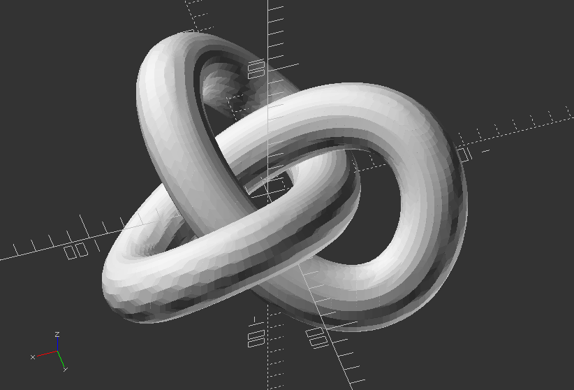
Math: Create several shape (explained below) with mathematical basic functions provided by OpenSCAD
// An EPITROCHOID is a curve traced by a point fixed at a distance "d" to the center of a circle of radius "r" as the circle rolls outside another circle of radius "R".
// An HYPOTROCHOID is a curve traced by a point fixed at a distance "d" to the center of a circle of radius "r" as the circle rolls inside another circle of radius "R".
// An EPICYCLOID is an epitrochoid with d = r.
// An HYPOCYCLOID is an hypotrochoid with d = r.
// See http://en.wikipedia.org/wiki/Epitrochoid and http://en.wikipedia.org/wiki/Hypotrochoid
// Beware the polar forms of the equations on Wikipedia...
// They are correct, but theta is measured to the center of the small disk!!
// There are several different methods for extruding. The best are probably the ones using linear extrude.
//===========================================
// Demo - draws one of each, plus some little wheels and sticks.
// Fun stuff to try:
// Animate, try FPS = 5 and Steps = 200
// R = 2, r = 1, d = 0.2
// R = 4, r = 1, d = 1
// R = 2, r = 1, d = 0.5
// What happens when you make d > r ??
// What happens when d < 0 ??
// What happens when r < 0 ??
//===========================================
//Set basic variables for all examples - Uncomment these for every example
$fn = 30;
thickness = 10;
R = 4;
r = 1;
d = 1;
n = 60; // number of wedge segments
alpha = 360*$t;
p = 16;
rb = 30;
twist = 250;
Create module for an Epitrochoid:
module epitrochoid(R, r, d, n, thickness) {
dth = 360/n;
for ( i = [0:n-1] ) {
polyhedron(points = [[0,0,0],
[(R+r)*cos(dth*i) - d*cos((R+r)/r*dth*i), (R+r)*sin(dth*i) - d*sin((R+r)/r*dth*i), 0],
[(R+r)*cos(dth*(i+1)) - d*cos((R+r)/r*dth*(i+1)), (R+r)*sin(dth*(i+1)) - d*sin((R+r)/r*dth*(i+1)), 0],
[0,0,thickness],
[(R+r)*cos(dth*i) - d*cos((R+r)/r*dth*i), (R+r)*sin(dth*i) - d*sin((R+r)/r*dth*i), thickness],
[(R+r)*cos(dth*(i+1)) - d*cos((R+r)/r*dth*(i+1)), (R+r)*sin(dth*(i+1)) - d*sin((R+r)/r*dth*(i+1)), thickness]],
faces = [[0, 2, 1], [0, 1, 3], [3, 1, 4], [3, 4, 5], [0, 3, 2], [2, 3, 5], [1, 2, 4], [2, 5, 4]]);
}
}
epitrochoid(R, r, d, n, thickness);
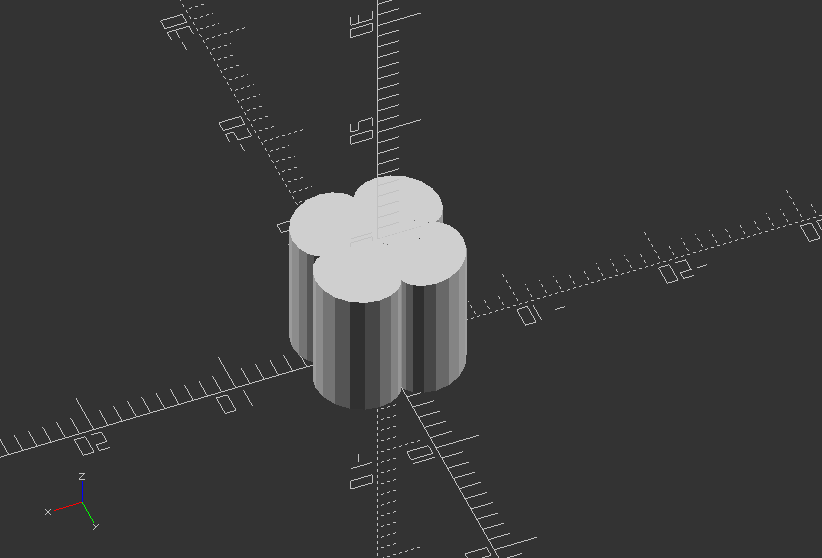
Create module for a Hypotrochoid:
module hypotrochoid(R, r, d, n, thickness) {
dth = 360/n;
for ( i = [0:n-1] ) {
polyhedron(points = [[0, 0, 0],
[(R-r)*cos(dth*i) + d*cos((R-r)/r*dth*i), (R-r)*sin(dth*i) - d*sin((R-r)/r*dth*i), 0],
[(R-r)*cos(dth*(i+1)) + d*cos((R-r)/r*dth*(i+1)), (R-r)*sin(dth*(i+1)) - d*sin((R-r)/r*dth*(i+1)), 0],
[0, 0, thickness],
[(R-r)*cos(dth*i) + d*cos((R-r)/r*dth*i), (R-r)*sin(dth*i) - d*sin((R-r)/r*dth*i), thickness],
[(R-r)*cos(dth*(i+1)) + d*cos((R-r)/r*dth*(i+1)), (R-r)*sin(dth*(i+1)) - d*sin((R-r)/r*dth*(i+1)), thickness]],
faces = [[0, 2, 1], [0, 1, 3], [3, 1, 4], [3, 4, 5], [0, 3, 2], [2, 3, 5], [1, 2, 4], [2, 5, 4]]);
}
}
hypotrochoid(R, r, d, n, thickness);
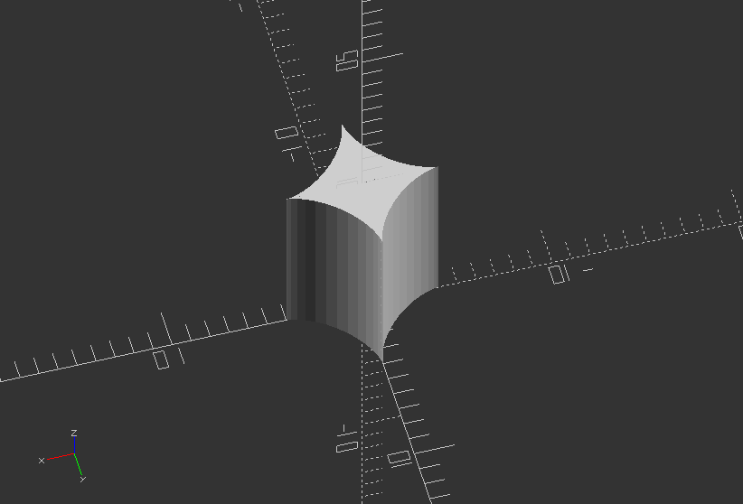
Create module for an Epitrochoid Wedge with Bore
module epitrochoidWBore(R, r, d, n, p, thickness, rb) {
dth = 360/n;
union() {
for ( i = [0:p-1] ) {
polyhedron(points = [[rb*cos(dth*i), rb*sin(dth*i),0],
[(R+r)*cos(dth*i) - d*cos((R+r)/r*dth*i), (R+r)*sin(dth*i) - d*sin((R+r)/r*dth*i), 0],
[(R+r)*cos(dth*(i+1)) - d*cos((R+r)/r*dth*(i+1)), (R+r)*sin(dth*(i+1)) - d*sin((R+r)/r*dth*(i+1)), 0],
[rb*cos(dth*(i+1)), rb*sin(dth*(i+1)), 0],
[rb*cos(dth*i), rb*sin(dth*i), thickness],
[(R+r)*cos(dth*i) - d*cos((R+r)/r*dth*i), (R+r)*sin(dth*i) - d*sin((R+r)/r*dth*i), thickness],
[(R+r)*cos(dth*(i+1)) - d*cos((R+r)/r*dth*(i+1)), (R+r)*sin(dth*(i+1)) - d*sin((R+r)/r*dth*(i+1)), thickness],
[rb*cos(dth*(i+1)), rb*sin(dth*(i+1)), thickness]],
faces = [[0, 1, 4], [4, 1, 5], [1, 2, 5], [5, 2, 6], [2, 3, 7], [7, 6, 2], [3, 0, 4], [4, 7, 3], [4, 5, 7], [7, 5, 6], [0, 3, 1], [1, 3, 2]]);
}
}
}
epitrochoidWBore(R, r, d, n, p, thickness, rb);
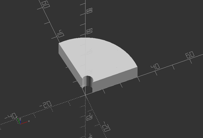
Create module for an Epitrochoid Wedge with Bore, Linear Extrude
module epitrochoidWBoreLinear(R, r, d, n, p, thickness, rb, twist) {
dth = 360/n;
linear_extrude(height = thickness, convexity = 10, twist = twist) {
union() {
for ( i = [0:p-1] ) {
polygon(points = [[rb*cos(dth*i), rb*sin(dth*i)],
[(R+r)*cos(dth*i) - d*cos((R+r)/r*dth*i), (R+r)*sin(dth*i) - d*sin((R+r)/r*dth*i)],
[(R+r)*cos(dth*(i+1)) - d*cos((R+r)/r*dth*(i+1)), (R+r)*sin(dth*(i+1)) - d*sin((R+r)/r*dth*(i+1))],
[rb*cos(dth*(i+1)), rb*sin(dth*(i+1))]],
paths = [[0, 1, 2, 3]], convexity = 10);
}
}
}
}
epitrochoidWBoreLinear(R, r, d, n, p, thickness, rb, twist);
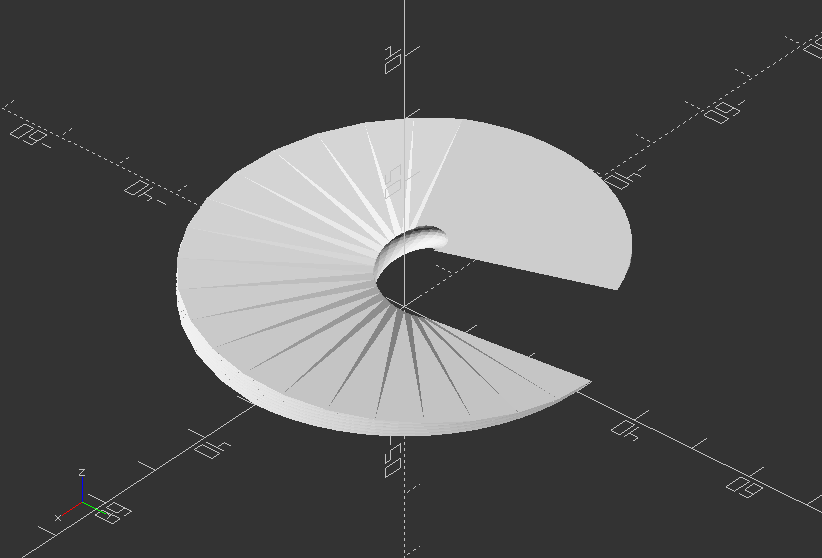
Create module for an Epitrochoid Wedge, Linear Extrude
module epitrochoidLinear(R, r, d, n, p, thickness, twist) {
dth = 360/n;
linear_extrude(height = thickness, convexity = 10, twist = twist) {
union() {
for ( i = [0:p-1] ) {
polygon(points = [[0, 0],
[(R+r)*cos(dth*i) - d*cos((R+r)/r*dth*i), (R+r)*sin(dth*i) - d*sin((R+r)/r*dth*i)],
[(R+r)*cos(dth*(i+1)) - d*cos((R+r)/r*dth*(i+1)), (R+r)*sin(dth*(i+1)) - d*sin((R+r)/r*dth*(i+1))]],
paths = [[0, 1, 2]], convexity = 10);
}
}
}
}
epitrochoidLinear(R, r, d, n, p, thickness, twist);
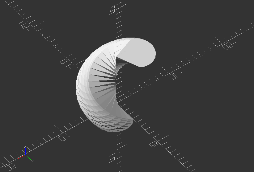
Create module for a Hypotrochoid Wedge with Bore
module hypotrochoidWBore(R, r, d, n, p, thickness, rb) {
dth = 360/n;
union() {
for ( i = [0:p-1] ) {
polyhedron(points = [[rb*cos(dth*i), rb*sin(dth*i),0],
[(R-r)*cos(dth*i) + d*cos((R-r)/r*dth*i), (R-r)*sin(dth*i) - d*sin((R-r)/r*dth*i), 0],
[(R-r)*cos(dth*(i+1)) + d*cos((R-r)/r*dth*(i+1)), (R-r)*sin(dth*(i+1)) - d*sin((R-r)/r*dth*(i+1)), 0],
[rb*cos(dth*(i+1)), rb*sin(dth*(i+1)), 0],
[rb*cos(dth*i), rb*sin(dth*i), thickness],
[(R-r)*cos(dth*i) + d*cos((R-r)/r*dth*i), (R-r)*sin(dth*i) - d*sin((R-r)/r*dth*i), thickness],
[(R-r)*cos(dth*(i+1)) + d*cos((R-r)/r*dth*(i+1)), (R-r)*sin(dth*(i+1)) - d*sin((R-r)/r*dth*(i+1)), thickness],
[rb*cos(dth*(i+1)), rb*sin(dth*(i+1)), thickness]],
faces = [[0, 1, 4], [4, 1, 5], [1, 2, 5], [5, 2, 6], [2, 3, 7], [7, 6, 2], [3, 0, 4], [4, 7, 3], [4, 5, 7], [7, 5, 6], [0, 3, 1], [1, 3, 2]]);
}
}
}
hypotrochoidWBore(R, r, d, n, p, thickness, rb);
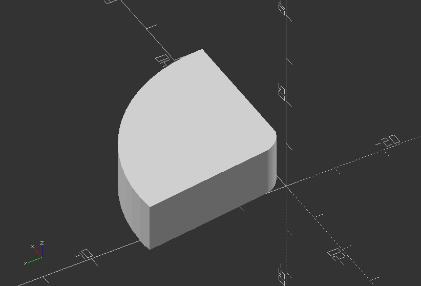
Create a Hypotrochoid Wedge with Bore, Linear Extrude
module hypotrochoidWBoreLinear(R, r, d, n, p, thickness, rb, twist) {
dth = 360/n;
linear_extrude(height = thickness, convexity = 10, twist = twist) {
union() {
for ( i = [0:p-1] ) {
polygon(points = [[rb*cos(dth*i), rb*sin(dth*i)],
[(R-r)*cos(dth*i) + d*cos((R-r)/r*dth*i), (R-r)*sin(dth*i) - d*sin((R-r)/r*dth*i)],
[(R-r)*cos(dth*(i+1)) + d*cos((R-r)/r*dth*(i+1)), (R-r)*sin(dth*(i+1)) - d*sin((R-r)/r*dth*(i+1))],
[rb*cos(dth*(i+1)), rb*sin(dth*(i+1))]],
paths = [[0, 1, 2, 3]], convexity = 10);
}
}
}
}
hypotrochoidWBoreLinear(R, r, d, n, p, thickness, rb, twist);
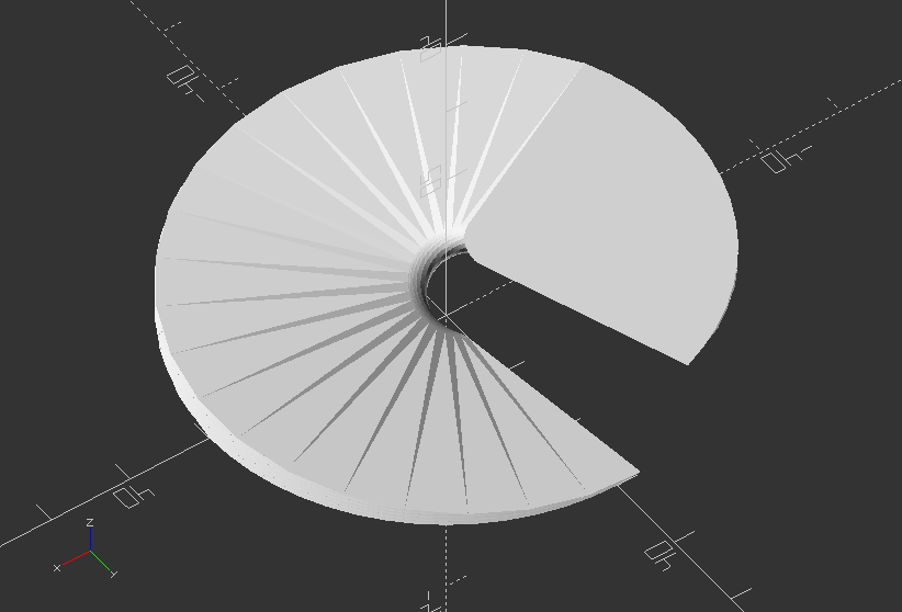
Create a Hypotrochoid Wedge
module hypotrochoidLinear(R, r, d, n, p, thickness, twist) {
dth = 360/n;
linear_extrude(height = thickness, convexity = 10, twist = twist) {
union() {
for ( i = [0:p-1] ) {
polygon(points = [[0, 0],
[(R-r)*cos(dth*i) + d*cos((R-r)/r*dth*i), (R-r)*sin(dth*i) - d*sin((R-r)/r*dth*i)],
[(R-r)*cos(dth*(i+1)) + d*cos((R-r)/r*dth*(i+1)), (R-r)*sin(dth*(i+1)) - d*sin((R-r)/r*dth*(i+1))]],
paths = [[0, 1, 2]], convexity = 10);
}
}
}
}
hypotrochoidLinear(R, r, d, n, p, thickness, twist);
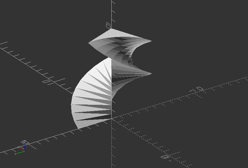
3.9. Variables
Plate / Bracket: Parametric design for furniture
//Module for single plate
module plate(width, length, thickness, screw_size, head_size) {
difference() {
cube([width, length, thickness]);
translate([width/2, length/2, 0])
cylinder(h=thickness, r=screw_size, $fn=30);
translate([width/2, length/2, thickness-4])
cylinder(h=4, r1=1, r2=head_size, $fn=30);
}
}
//Module for bracket
module bracket(length, width, thickness, screw_size, head_size) {
plate(width, length, thickness, screw_size, head_size);
translate([width,-thickness,thickness])
rotate([90, 0, 180])
plate(width, length, thickness, screw_size, head_size);
translate([0, -thickness, 0])
cube([width, thickness, thickness]);
}
//Call the plate object
bracket(50, 50, 4, 3, 6);