1. Preparation
BlocksCAD
There is not much preparation necessary to prepare for this course.
BlocksCAD Offline: Menu >> Education >> BlocksCAD
One simple way is using the Online version of BlocksCAD. The browser you are going to use needs WebGL support. Simply test the online version by dragging a sphere onto the workspace and press "RENDER". The sphere then should appear in the 3D preview.
3D Printer
In case you already have a 3D printer and/or you want to learn how to prepare your 3D models to be printed. You definitely need to slice your 3D models into layers according to your printers settings.
A controlling software is not necessary, if you use a sd card to transfer the sliced model file .gcode directly to the printer. Most printer can handle it through their in-built software.
You will find more about this topic in Section 5.
Software for PC - Linux, Windows, Mac
There is one free open-source slicer software installed on this Moodle Server Distro:
Menu >> Education >> Prusa Slicer
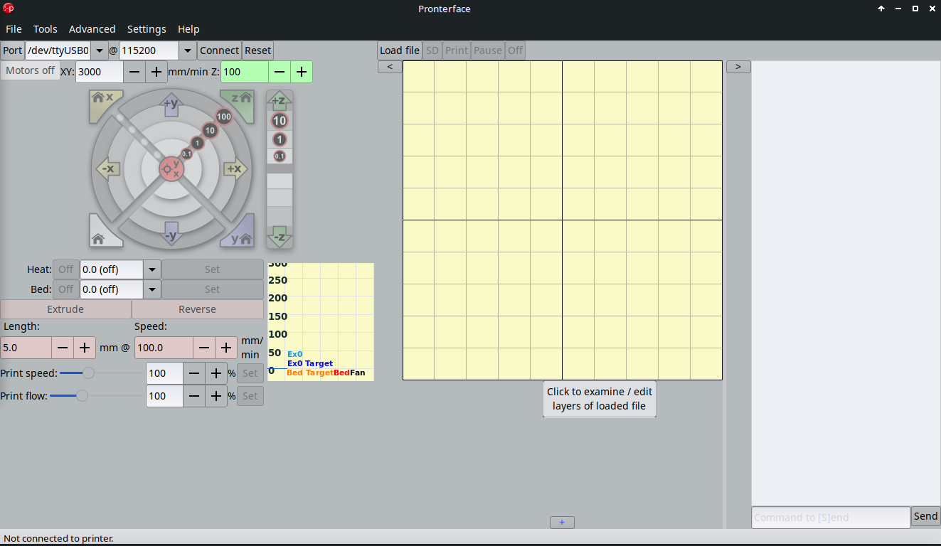
Furthermore, there is an open-source software installed to control 3D printer via usb :
Menu >> Education >> Pronterface
Otherwise, you can download and install both software here, if you want to use another Distro:
and here:
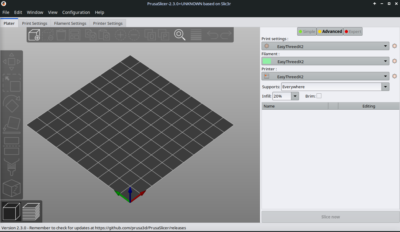
Prusa Slicer
Pronterface
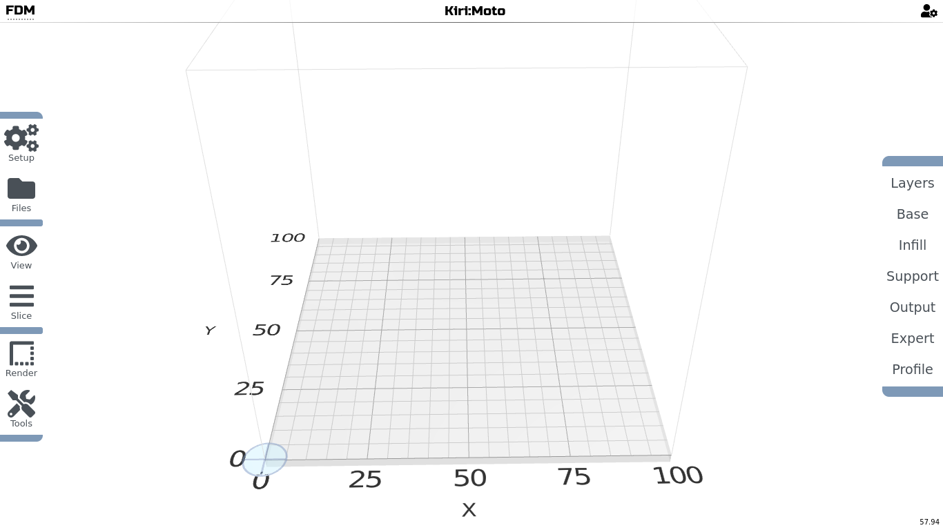
One simple way of slicing your models, that does not need any installation, is Online GCODE slicer kiri:moto - Free to use. However, this software is only available with Internet access!
Go to the site, upload your .stl file you exported from BlocksCAD, enter the details of your printer and slice it into .gcode format. This file you can then upload to your printer directly or with a printer control software.
Software for Android
There is no proper slicing software for Android at the moment, so kiri:moto is still the best guess of getting your models sliced for your printer.
Unfortunately, you will need internet connection in order to use it!
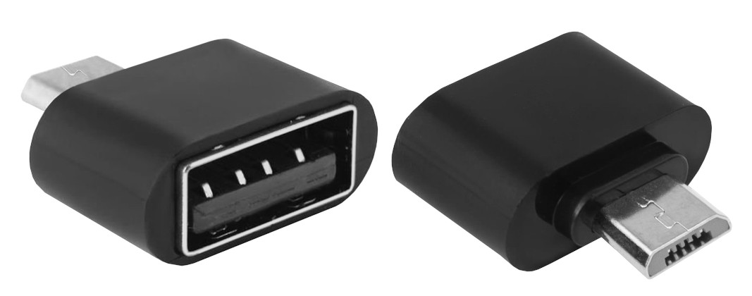
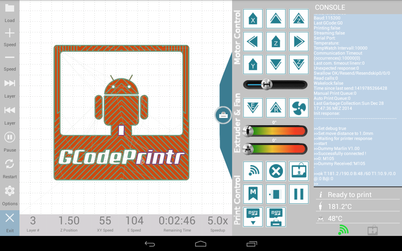
However there is a cheap and well done 3D printer controlling software for Android. If you use an usb adaptor, you will be able to connect your 3D printer directly to your Android Tablet and control the 3D printer.
Adapter:
The recommended control software:
2.1. What is OpenSCAD?
OpenSCAD is a free software application for creating solid 3D CAD (computer-aided design) objects. It is a script-only based modeler that uses its own description language; parts can be previewed, but cannot be interactively selected or modified by mouse in the 3D view. An OpenSCAD script specifies geometric primitives (such as spheres, boxes, cylinders, etc.) and defines how they are modified and combined (for instance by intersection, difference, envelope combination and Minkowski sums) to render a 3D model. As such, the program does constructive solid geometry (CSG). OpenSCAD is available for Windows, Linux and macOS.
2.2. What is BlocksCAD?
BlocksCAD is an education technology company dedicated to creating tools that help students of all ages pursue their love of science, technology, engineering, art, and math (STEAM). Our signature product, BlocksCAD, is a cloud-based 3D modeling tool that encourages users to learn math, computational thinking and coding concepts through visualization and designing models to be 3D printed.
- BlocksCAD is a scratch-like programming environment to create 3D objects.
- It was developed with the sponsorship of the Defense Advanced Research Projects Agency (DARPA) and the code is licensed GPLv3 or later.
- BlocksCad code will generate OpenSCAD code that one can export (code button on top right or the design window). Otherwise the STL model will be generated on the server. Playing with BlocksCAD is therefore also a way to learn OpenSCAD.
2.3. Why using Code?
There basic advantages in learning coding:
- Using Python or other close-to-human languages are easy to learn, especially if you are younger
- Enhances problem solving skills through logical thinking in both linear and non-linear ways
- Programming skills are transferable to many different areas in life
- Opens opportunities to invention and innovation by giving a tool to express thoughts and ideas
- Using coding with 3D modeling helps kids to have fun with math
There are many CAD (Computer Aided Design) software available. OpenSCAD is unique with its own scripting language, and is a brilliant starter into CAD Modeling and coding. The code you are using is so close to human understanding, that you theoretically would not need a computer to create blueprints / sketches from it. Just read the script code without one of the axis, thus creating different views, like front view, side view, top view s.o.
Here some basic pros and cons of using OpenSCAD as a CAD modeling tool:
| | | | --- | --- | | Pro | Cons | | Easy to learn | Difficult creating organic shapes | | Easy precision modeling | Non-Traditional UI | | Small file size | Moving objects only via code | | Vivid helping community | First need to learn coding | | Complex modeling with modules | Limited Preview Functionality | | Can be imported into FreeCAD | Animation very tricky to not possible |
Most of all: It is fun to work with it once you figured it out!
2.4. How does BlocksCAD work?
BlocksCAD is a web-browser application, that does not need to be installed on your computer. There is an offline version available that needs a simple web-server script to run in order to create 3D/2D text in BlocksCAD. The graphical interface of BlocksCAD is fairly simple, so lets get through it.
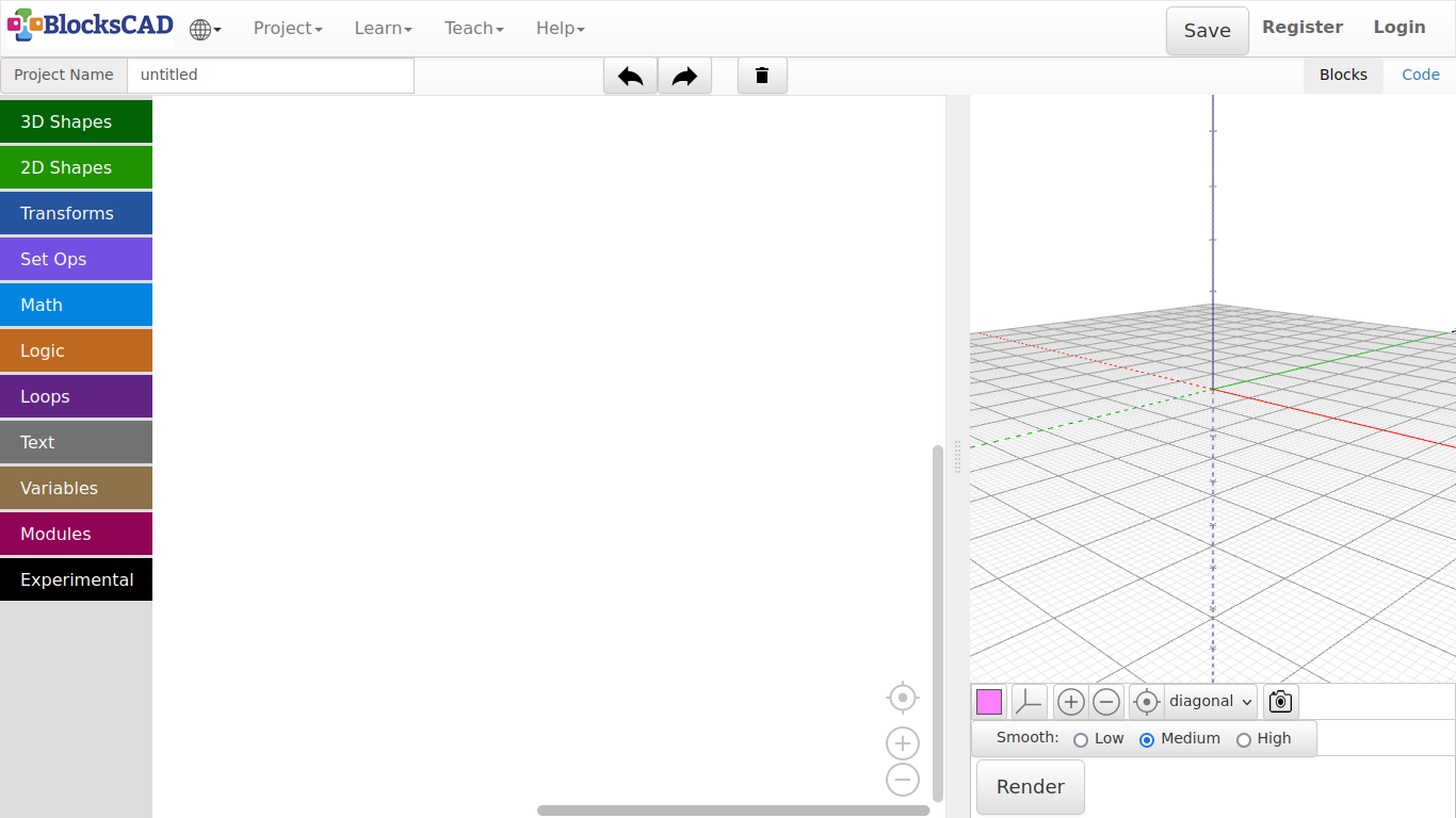
Header
The header is the main menu with several subsections. I will only mention the section we are going to use.
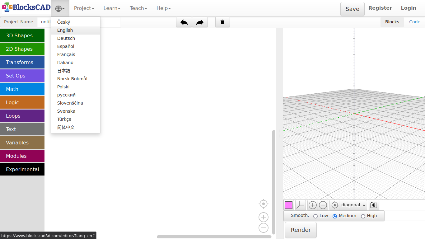
- Wired sphere >> Change language
- Projects >> Create new project, save and open files with different formats
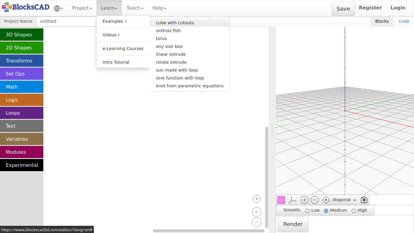
- Learn >> Examples, tutorials and videos
- Project Name >> Give your current project a name (Default: untitled)
- Left Arrow Icon >> Undo
- Right Arrow Icon >> Redo
- Trashcan Icon >> Delete workspace
- Blocks | Code >> Switch between blocks editor and OpenSCAD code view
Left Panel
This panel is the blocks menu, which has several subsections. A Block contains a certain functions, that generates the represented OpenSCAD code.
- 3D Shapes >> Basic 3d primitives
- 2D Shapes >> Basic 2d primitives
- Transforms >> Transform embedded shapes
- Set Ops >> Boolean operators
- Math >> Mathematical operators
- Logic >> Conditional operators
- Loops >> Loop block
- Text >> 3D and 2D Text related blocks
- Variables >> Variable blocks for parametric designs
- Modules >> Blocks to create modules
Center Panel
The center panel is basically the workspace. You drag in and combine all block on in this place. If you want to erase blocks, just drag it far to the Left out of the window, or press Del.
- Icon Pointer >> Centers the view of the workspace
- Icon + >> Zooms in
- Icon - >> Zooms out
You can use the Left Mouse Button to pan, 2 finger gesture to zoom, and the Right Mouse Button to open a sub menu.* Use the finger to pan, the scrolling wheel to zoom in and out, and hold the finger for 2-3 second to open a sub menu.***
Right Panel
This is the 3D view port to see the generated 3D objects. The changes appears, after the button *Render* is pressed.
You can use the Left Mouse Button to rotate, the scrolling wheel (or middle mouse button) to zoom in and out, and the Right Mouse Button to pan. Use the finger to pan, the scrolling wheel to zoom in and out, and hold the finger for 2-3 second to open a sub menu.
- Colored Square >> Change the color, with which your object is previewed
- 3 lines Icon >> Switches on/off Grid view
- Icon + >> Zooms in
- Icon - >> Zooms out
- Icon Pointer >> Centers the view of the workspace
- Render >> Creates a preview version of everything on the workspace
- Generate STL >> Exports preview as a 3D Mesh in .stl format
Lets try things out, so you learn the basic workflow in BlocksCAD:
Change a language using the selection under wired sphere icon (Default: English)
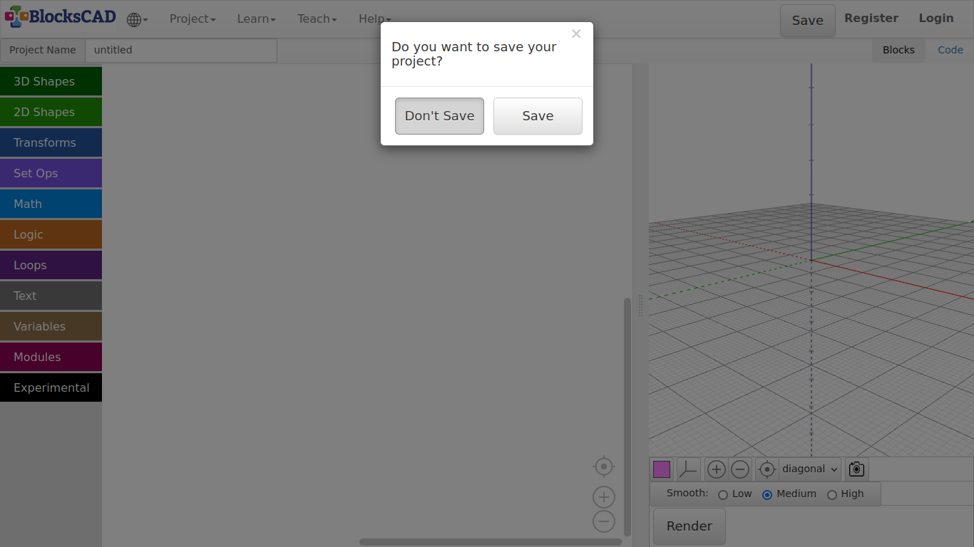
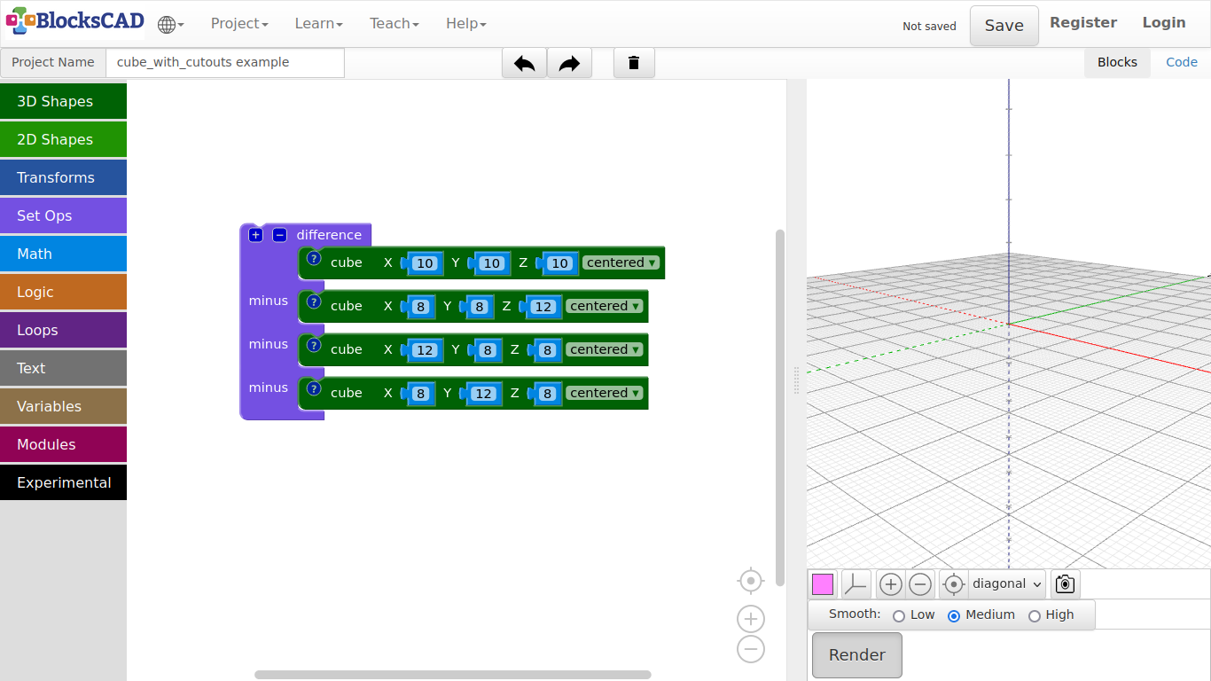
Try the first example under Learn >> Examples >> cube with cutouts
If BlocksCAD ask, if you want to save the previous code, press Don't Save.
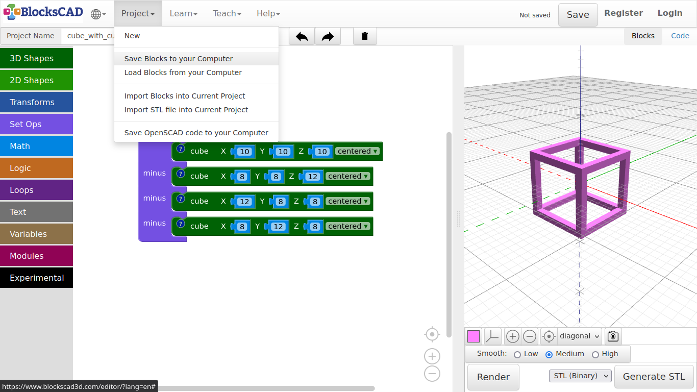
Press Render in the right panel to see, what the code is doing
Save the blocks on your workplace Project >> Save Blocks to your Computer
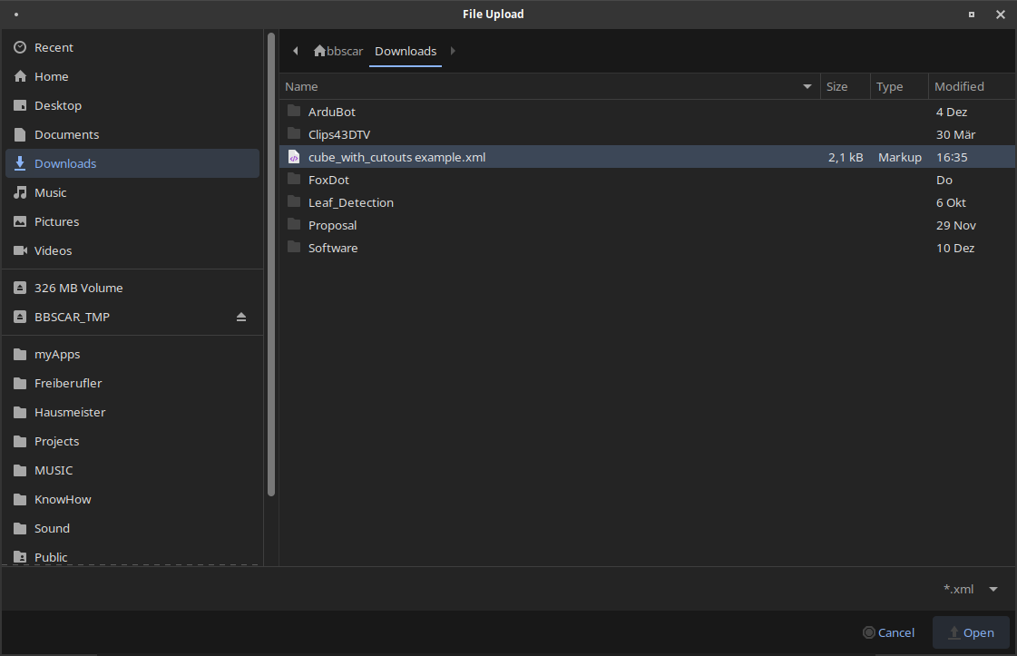
Now reopen your saved project Projects >> Load Blocks from Computer

As you can see, it saved it with the Project Name. Select it and press Open
Now press Code on right side of the header panel Blocks | Code. You will see the actual code, that is created by the blocks.
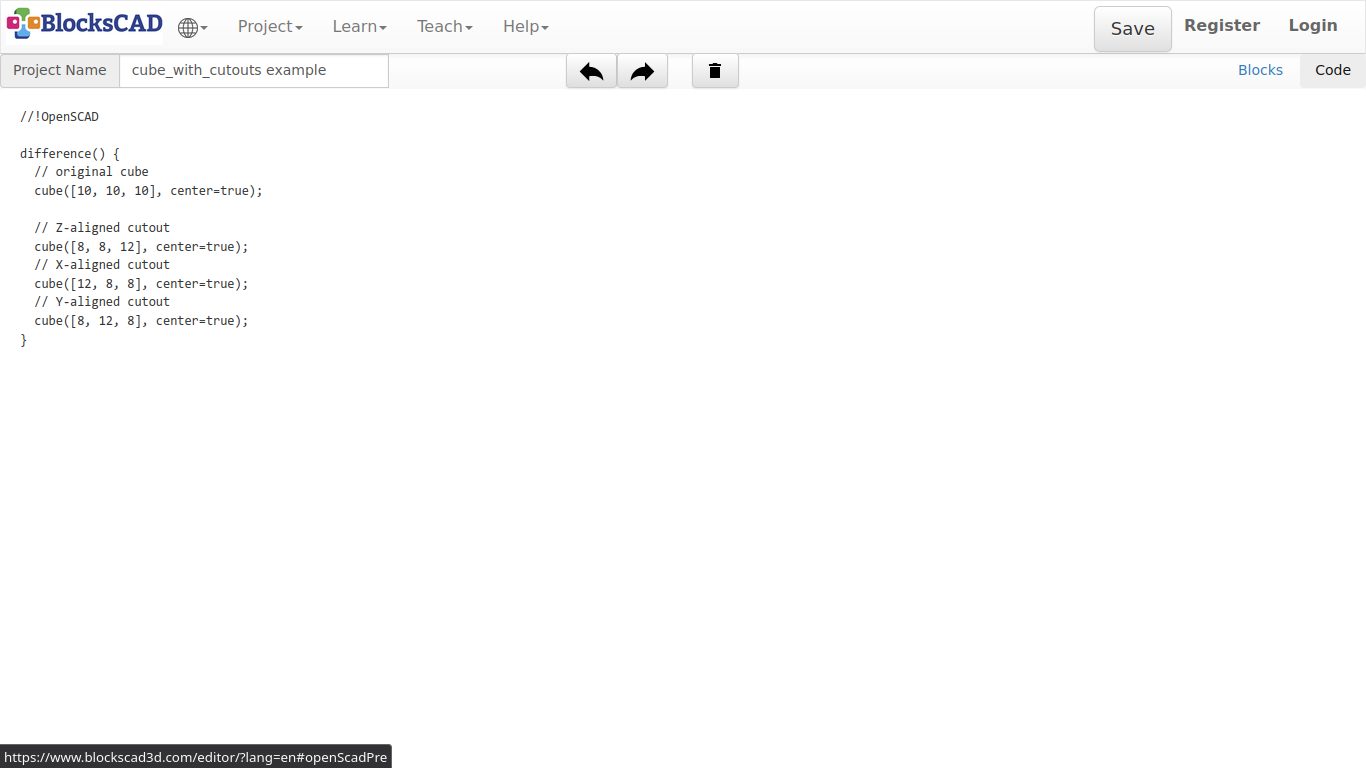
Now press Blocks, then press Projects >> Save OpenSCAD code to your Computer to export the code you have seen to your computer.
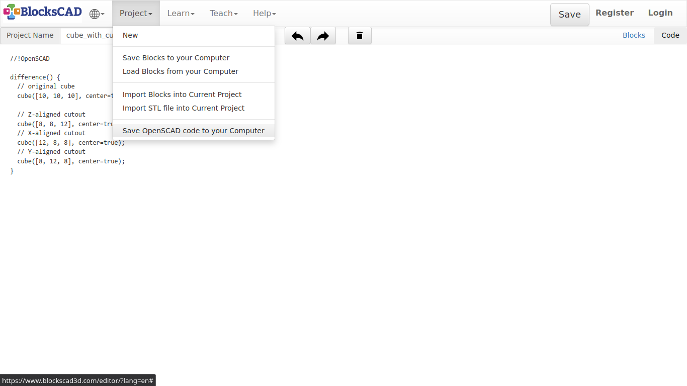
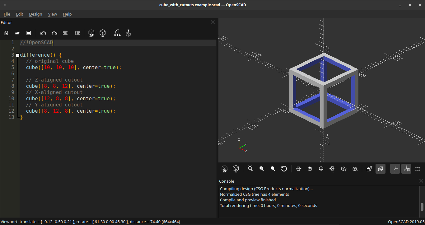
As you probably do not have OpenSCAD installed yet, check out the image to see, how it will look like in OpenSCAD.
Menu >> Education >> OpenSCAD
OpenSCAD
If you want to export the rendered preview as an object, press in the right panel Generate STL.
Do not forget to name your project first!
The exported STL file is relevant, if you want to continue and print it with a 3D printer, CNC Router or Laser cutter.
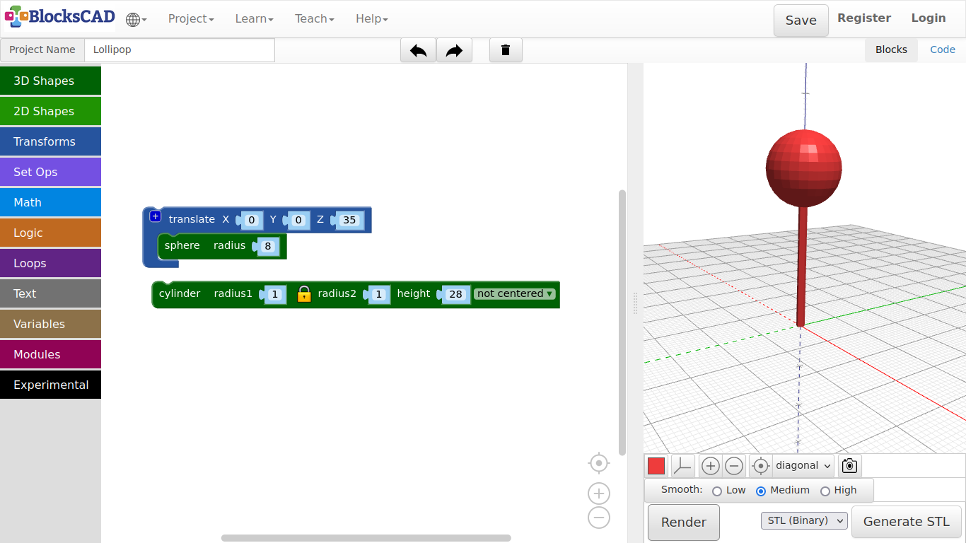
3.1. Lollipop
-
Start wit a new project by pressing Projects >> New
-
Drag and drop a sphere from 3D Shapes into our workspace.
-
Press Render and change your point of view by clicking LMB and move mouse around.
-
If your object is out of sight, use the pointer icon to get it back.
The sphere shows 10, which means 10 mm or 1 cm radius. The diameter of the sphere is therefore?...2 cm or 20 mm.
- Change the number of the sphere to 30 and render again.
Now the sphere is 6 cm in diameter.
But hold on, how can I see the difference?
To see the difference, lets put a second sphere aside. But first, in order to move the sphere as aside, we need another piece called.
-
Drag a translate block into the workspace. You will find it in Transforms.
-
Now enter 50 into the first cell with the name X.
-
Now drag another sphere from the 3D Shapes menu, and plug it into the translate slot. Press Render again!
See! The new sphere is now created 50 mm aside our first sphere, alongside the red line. The red line is the x axis, the green line is the y axis and the blue line is the z axis.
Change the numbers in translate and see how the sphere is moving around with the changes you made. Do not forget to press "Render".
-
Delete the first sphere by clicking on it and drag it left out of the scene, or press Delete key, while keeping the sphere within the translate block.
-
Now enter new values to translate as follows: X = 0, Y = 0, Z = 35.
-
Change the sphere radius to 8 millimeter.
-
Now drag and drop another cylinder block from 3D Shapes onto your workspace.
-
Enter the number 1 for radius1 and 28 for height.
-
Press Render again.
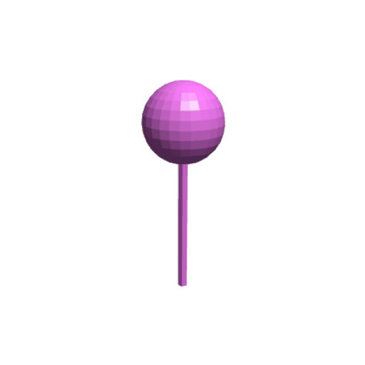
A voila, a lollipop!
-
Name your project as Lollipop under Project Name:.
-
Save your project under Project >> Save Blocks to your computer.
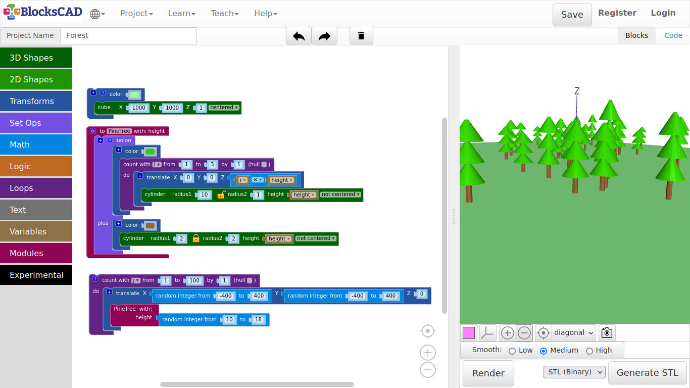
3.10. Forest
Now we will use the module "Pine Tree", we created in the last tutorial to create a forest.
- Open a new project and name it Forest.
Next we will import our tree module.
- Go to Project >> Import blocks into Current Project, select PineTree.xml and click Open.
As we did not do not have the module presenting block on our workspace, pressing Render should show nothing. Lets build the forest ground.
-
Drag and drop one cube from 3D Shapes, and one color from Transforms.
-
Change the values of cube to X = 1000, Y = 1000, Z = 1, centered, and plug it into color.
-
Now choose the color for your ground by changing it in color. I choose a light green.
-
Press Render.
This is the place we are going to spread a hundred trees randomly. The floor is 1000 from side to side, the random generator will distribute the tree within 800 of both sides.
Lets create 100 trees randomly distributes across the ground!
-
Drag and drop one count with from Loops, one translate from Transforms, two random integer from Math, and PineTree from Modules.
-
Plug in the PineTree block into translate.
-
Plug in one random integer to X of translate, and one random integer to Y of translate.
-
Change the values of both random integer to from: -400, to: 400.
-
Plug in the translate block with PineTree into count with.
Each time you plug in a new "count with" the index will change. It always starts with "i", then "j", "k", so on. You also can use your own name or variable. We stick with "j" for now.
-
Change the value to in count with to 100, as we want to build 100 trees.
-
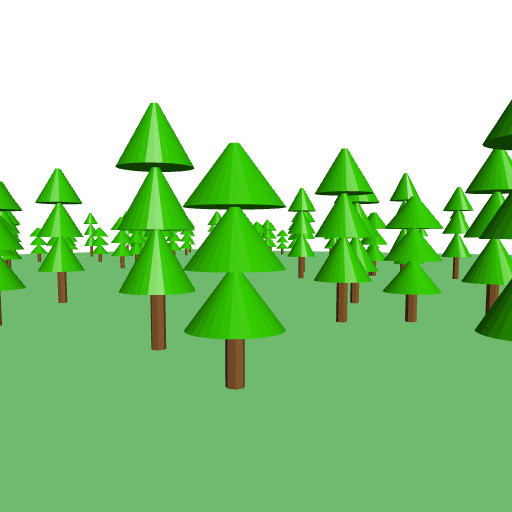
Press Render.
Be patient!* This is quite some task for BlocksCAD.***
There is your forest! But all the trees have the same height.
Lets create some more variety!
For that, we need to modify our module.
-
Press on the gear icon of the to Pine Tree block.
-
Drag n drop input name on the left into inputs on the right.
-
Rename the input to height.
Now check your module block in "count with j".
Can you see the new slot called "height"?
But this is not the only new thing, that got created.
-
Drag and drop three height from Variables, and one random integer from Math onto your workspace.
-
Now plug in all three height blocks in your to PineTree module. Two for each height value of the two cylinder, and one under translate instead of 10 in i x 10.
-
Plug the random integer block into the new slot of the module representing block PineTree as height input.
-
Change the values of random integer to from: 10, to: 18.
-
Press Render.
Again, be patient, it will take a while!
Exercise:
Import the house, pavilion, umbrella, and your own modules into the scene and create an image from your modeled "House in the woods" scene. Move the camera into a nice position and press the camera icon in the 3D viewer to save the image.
Tip:
- Reduce the random integer area and tree counts, so you have a free area on the floor.
- Drag and drop translate, rotate, and scale accordingly to move your modules and objects around
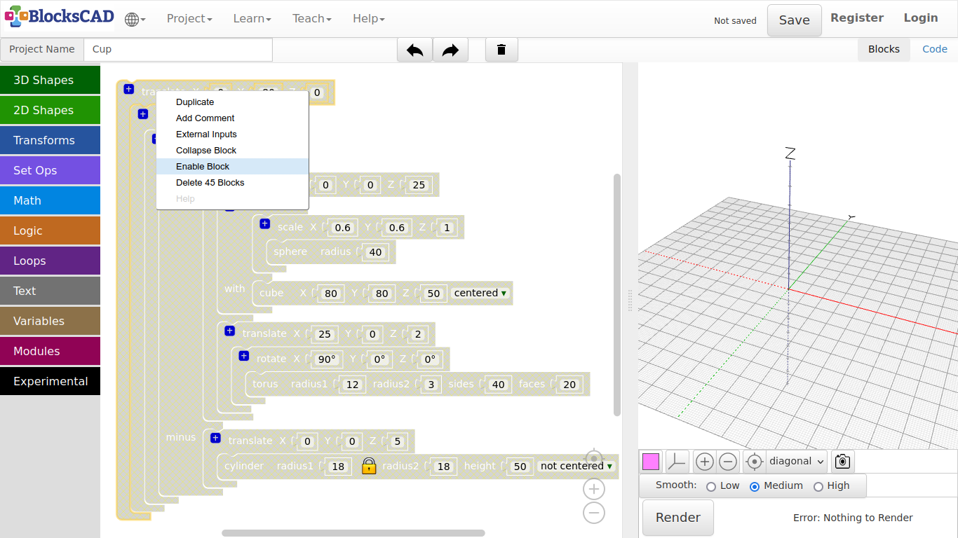
- Disable the representing "Pine Tree" block to avoid the long render times. Can you remember how?
Select the block and press the right mouse button or hold your finger till the Pop-up menu appears. Press on "Disable Block". Do the same thing to enable it again. The choice will be "Enable Block".
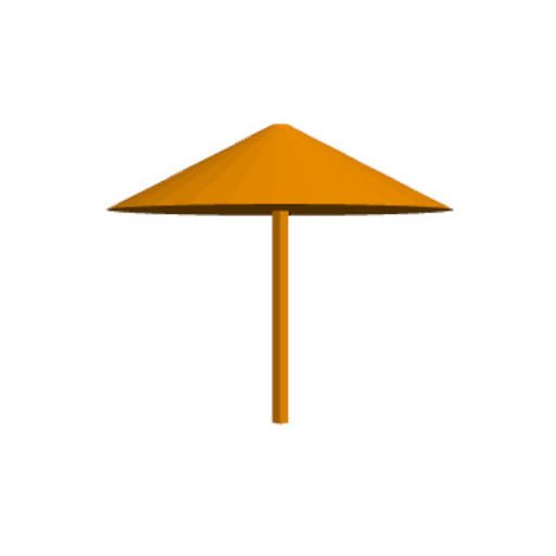
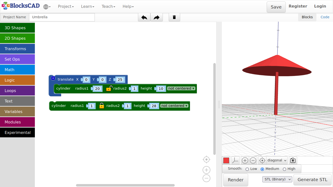
3.2. Umbrella
-
Open your Lollipop project under Project >> Open Blocks from your computer
-
Change the name of this project to Umbrella under Project Name:
-
Now click on the sphere and move it out of the workspace.
-
Keep the translate block.
-
Now drag another cylinder from 3D Shapes into the scene and plug it into translate, and press Render.
Can you see the space between the 2 cylinders?
-
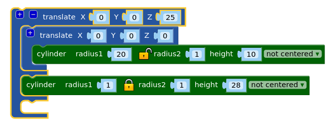
Lets change it by entering the height of the first cylinder to the translate module Z = 25.
-
Press Render.
Ok, now lets make an umbrella out of it!
The cylinder block has radius1 and radius2 for the bottom circle and the top circle. The value of radius2 is bound to radius1 by default. The lock icon between the 2 values represent this connection.
-
Press the little lock icon to unlock the connection between radius1 and radius2 of the cylinder block, that is plugged into the translate block.
-
Change the value of radius1 to 20, and radius2 to 1.
-
Press Render again!
Now we’ve got it! There is our umbrella.
- Save the project under Project >> Save Blocks to your computer.
Exercise:
Try all different 3D shapes, change the values and use translate to move them around in space! Let us see, what you can make of it!
Tip: You can plug translate blocks into each other, and press *+* to add more slots for objects. This way you can group objects together and move all at once!
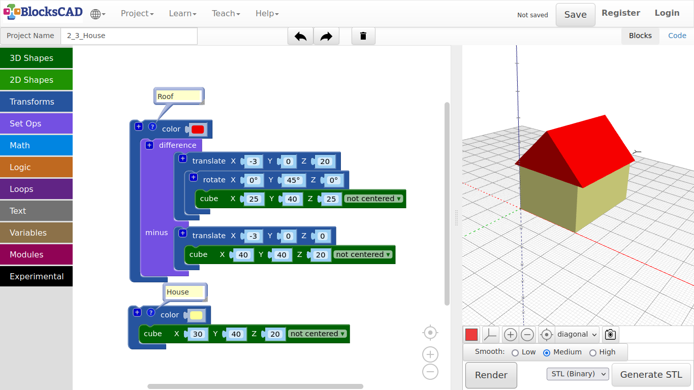
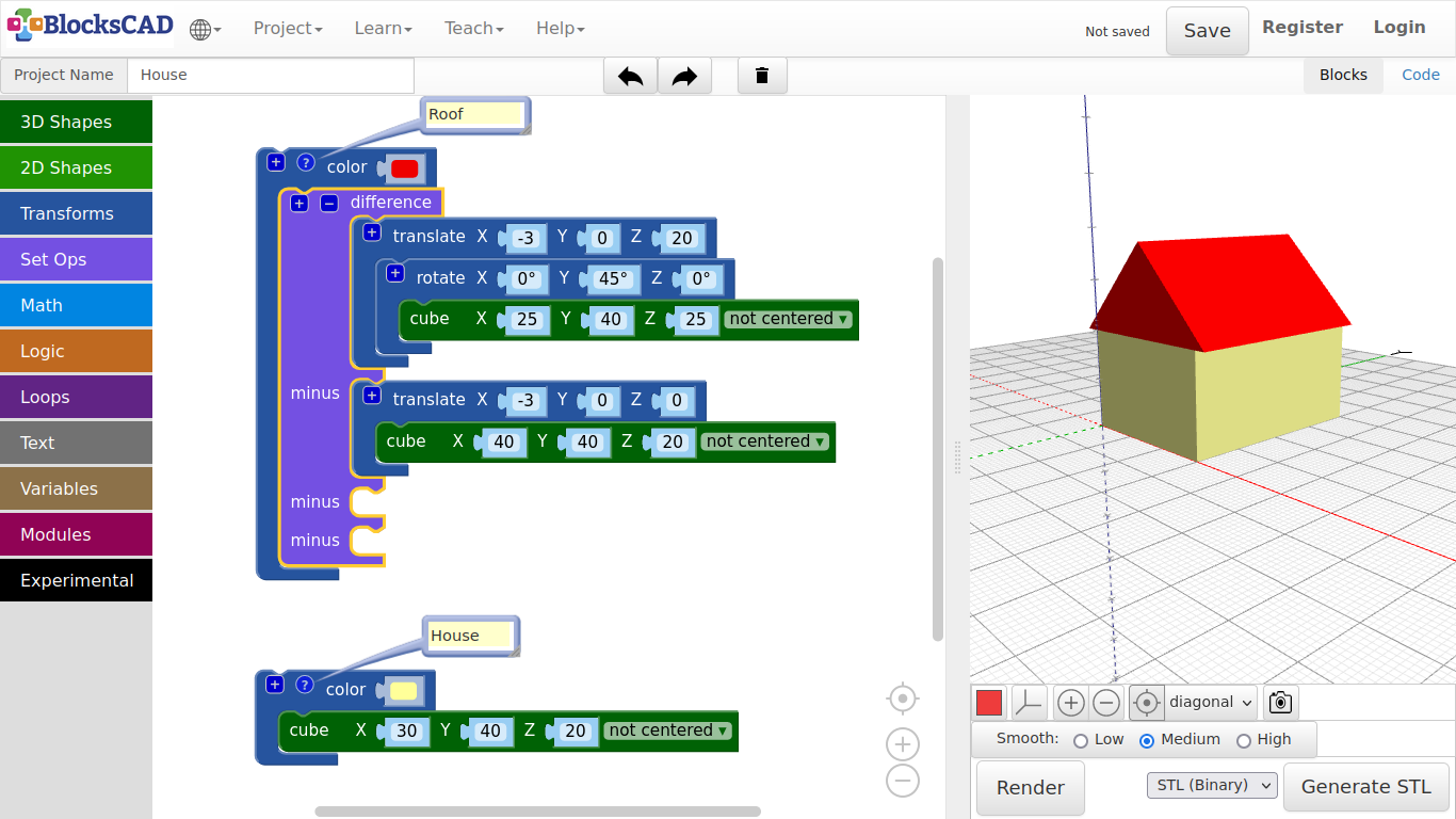
3.3. House
-
Lets start with Project >> New again.
-
Name this project House.
-
Drag and drop a cube from 3D Shapes onto the workspace.
-
Give it following values X = 30, Y = 40, Z = 20.
-
Press Render.
Now, we want to get a roof on top of our house.
-
Drag and drop one cube from 3D Shapes, one translate and one rotate from Transforms.
-
Change the values of the new cube to X = 25, Y = 40, Z = 25.
-
Next, plug the cube block you just changed into the rotate block.
-
Change the rotation of Y to 45 degree.
You will see the wheel, that you can turn to 45 degrees along the axis you selected. You also can enter the number directly.
-
Now plug this rotate block into the translate block.
-
Change the values of translate to X = -3, Y = 0, Z = 20.
-
Press Render.
The roof is on the right place, but there is something wrong!
We need to cutout the lower part of the roof cube, so it really looks like a roof.
-
Drag and drop one cube block from 3DShapes, one translate block from Transforms, and one difference block from Set Ops onto your workspace.
-
First change the values of the new cube to X = 36, Y = 40, and Z = 20.
-
Then plug it into the new translate block and change its values only in X to -3.
-
Press Render.
This new cube represents the part we want to cut away from the roof cube. For this we have "difference". It cuts away the 2nd part named "minus" from the 1st part.
-
Plug the roof cube block inclusive translate and rotate into the first section of difference.
-
Then plug the cut out cube inclusive its translate block into difference section named minus.
-
Press Render again.
Did it cut away the lower part? Does it look like a roof now? Now lets give the house and roof a different color!
-
Drag n drop two color blocks from Transforms onto your workspace.
-
Plug in the house cube and the roof difference block each into one color block.
-
Click on the little color squares and choose your own color.
-
Press Render.
To keep things in check, you can name each of the blocks.
-
Select each color block, click the right mouse button or use finger touch to open a little pop-up menu.
-
Select Add comment. You will see a little question mark afterwards.
-
Click on that, and type in House and Roof.
Keep on commenting the parts your create. It is helpful for you and others to understand your designs better, especially when it is going to be more complicated. Commenting is a very important part in programming. It is like a friend, that whispers you the right message when you need it.
- Save your project under Project >> Save Blocks to your computer.
Exercise:
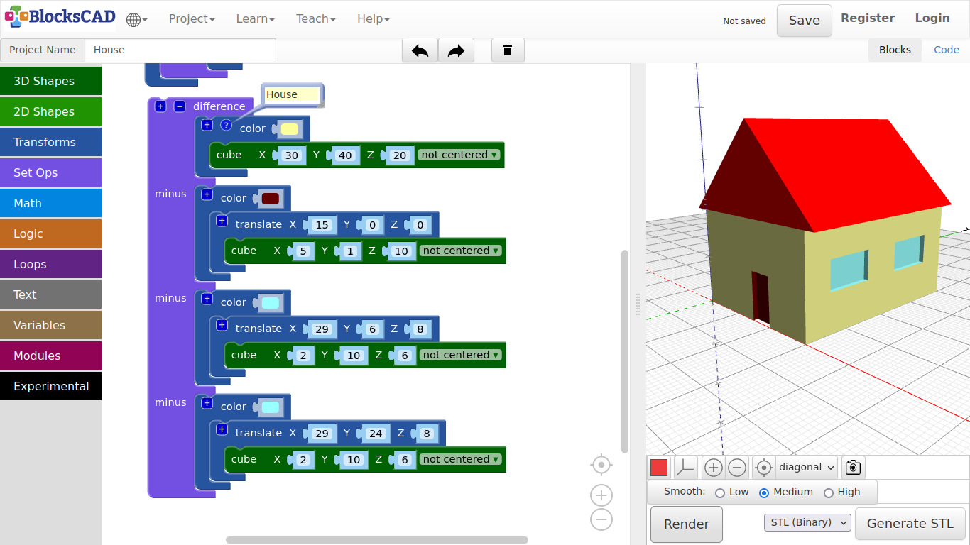
Use cube, translate, rotate, and difference to add doors, windows, or a chimney to the house.
Tips:
- You can use the “+” symbol to add more slots to difference, so it will cut out more boxes at once.**
- You can use RMB (Right Mouse Button) or finger touch to open the Pop-up-menu and choose “Duplicate” to get copies of your blocks.
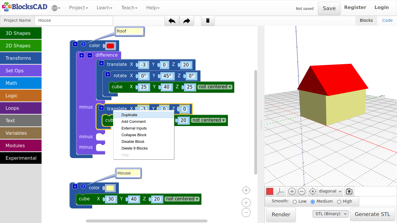
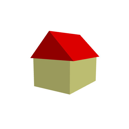
Here an example to help you getting started:
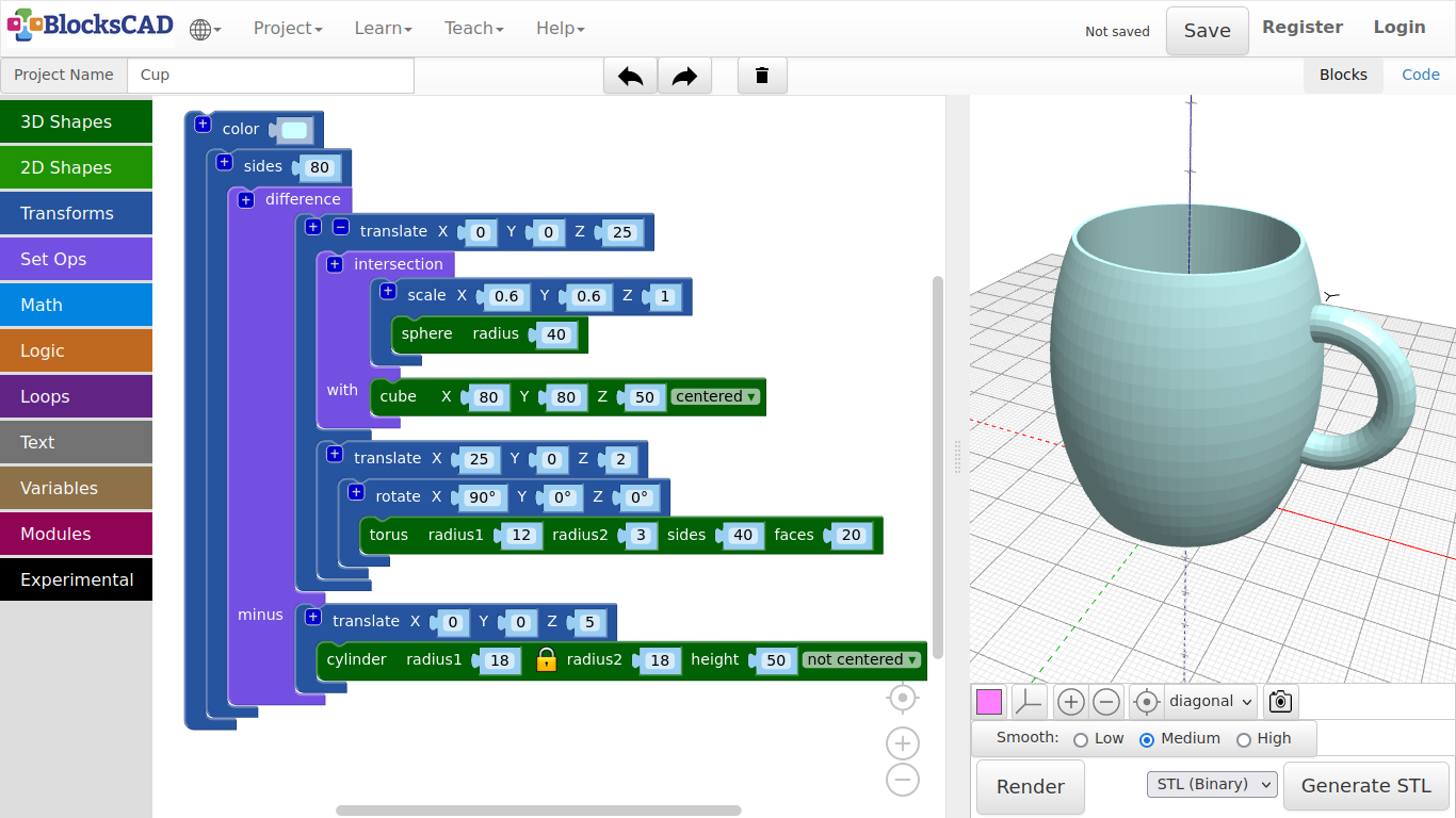
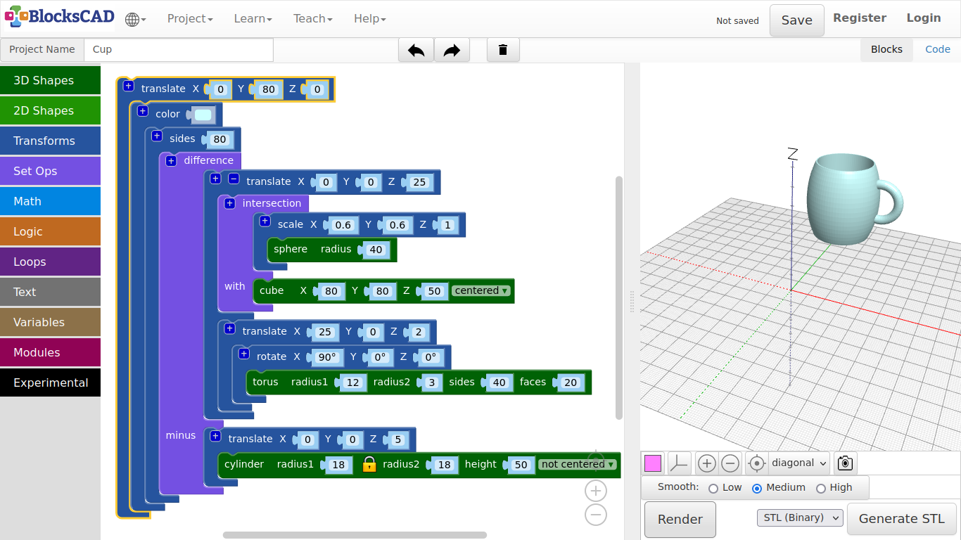
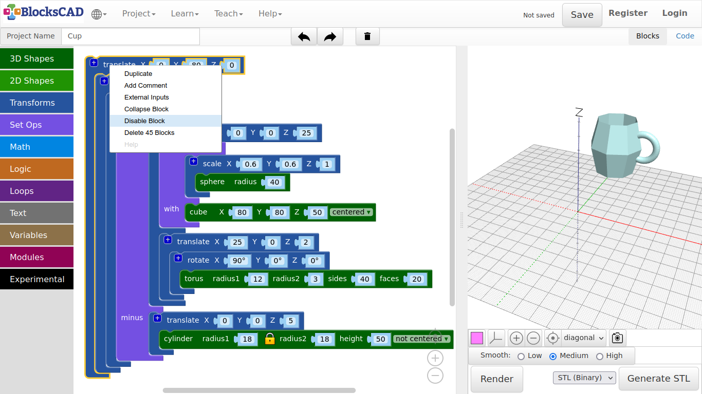
3.4. Cup
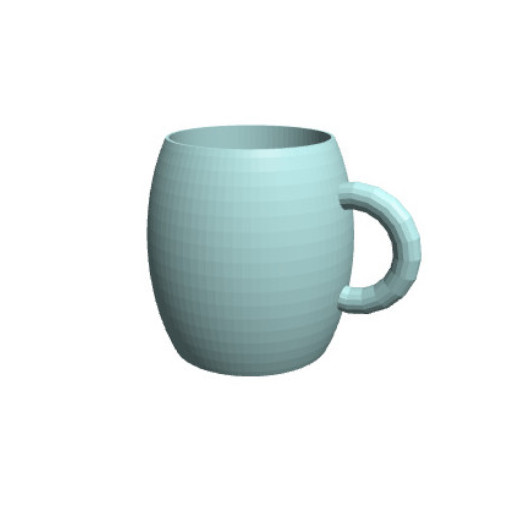
With this design, I will introduce you to a new method you can use called intersection
-
Drag and drop one intersection block from Set Ops, one translate and one scale block from Transforms, one sphere block and one cube from 3D Shapes.
-
Lets start with the sphere by change the radius to 40.
-
Plug the sphere into scale and change the values there to X = 0.6, Y = 0.6, Z = 1.
-
Press Render.
To create a cup, we want to cut off the top and the bottom. While "difference" cuts away the blocks that is represented, "intersection" cuts away anything else but the represented part.
Lets build a cube of the area, that will remain after the cut!
-
Change the values of the cube to X = 80, Y = 80, Z = 50.
-
Change the cube option not centeredto centered.
The block intersection will keep everything, that is covered by the second object under "with".
-
Plug the scale block with the sphere into the first position of intersection.
-
Then move the cube into the second position named with.
-
Press Render.
See!? It should look like a barrel now!* Ok, lets move the barrel up with a translate block.***
-
Connect the intersection block with translate.
-
Change the translate block value Z to 25.
-
Press Render.
Next we will use a cylinder to cut out the inside of the cup. Now this is a block you already used. What is it? … difference!
-
Drag and drop one cylinder block from 3D Shapes, one translate from Transforms, and one difference block from Set Ops onto your workspace.
-
Change the values of the cylinder to radius1 = 18, and height = 50.
-
Plug the cylinder into the new translate block.
-
Change the Z value of translate to 5.
-
Now take the translate block with the intersection and plug it into the first position of the difference block.
-
Plug the translate block with the cylinder in the second one called minus.
-
Press Render.
Last but not least, we need a handle for our cup.
-
Drag n drop one torus block from 3D Shapes, one rotate and one translate block from Transforms.
-
Change the values of the torus to radius1 = 12, radius2 = 3, sides = 40, and faces = 20.
-
Plug the torus into the rotate and change its X value to 90 degrees.
-
Connect this to translate, and change its values to X = 25, Y = 0, Z = 2.
-
Press Render.
Ok, you will see the handle on the bottom. The torus goes through the cup, but we want to cut this out as well. We need to implement the torus into the difference block. You can do this by adding a slot in translate of the intersection block.
-
Press the + sign of the translate block in the first position of difference, and plug in the entire torus block inclusive rotate and translate.
-
Press Render.
-
Add a color block from Transforms, and plug the entire block section into it.
-
Save your project under Project >> Save Blocks to your computer.
Before you create your own objects in the next exercise, I want to show you something, that can become very useful. Lets create a new project, do not forget to save your cup project.
-
Start wit a new project by pressing Projects >> New.
-
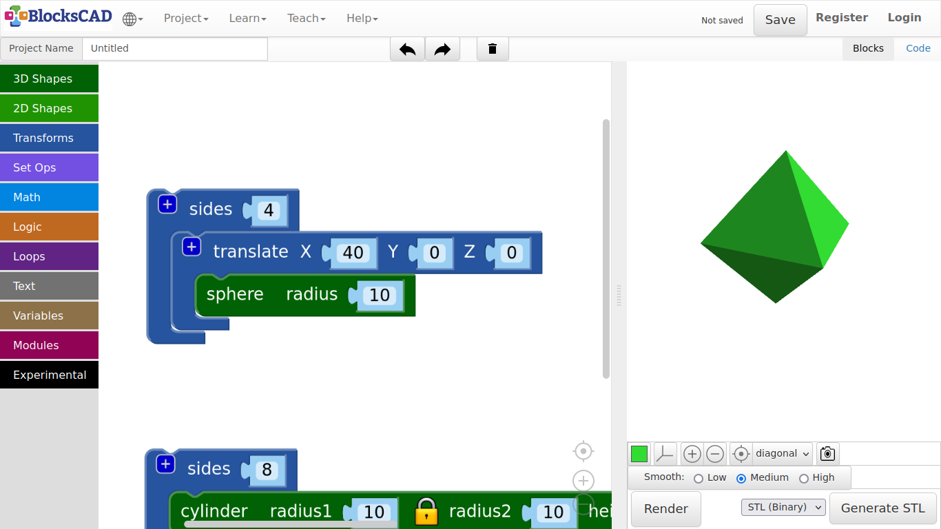
Drag n drop one sphere and one cylinder from 3D Shapes, one translate block and two sides blocks from Transforms onto your workspace.
-
Plug the sphere into translate and change the X value to 40.
-
Then plug translate with the sphere into one of the sides block and change its value to 4.
-
Press Render.
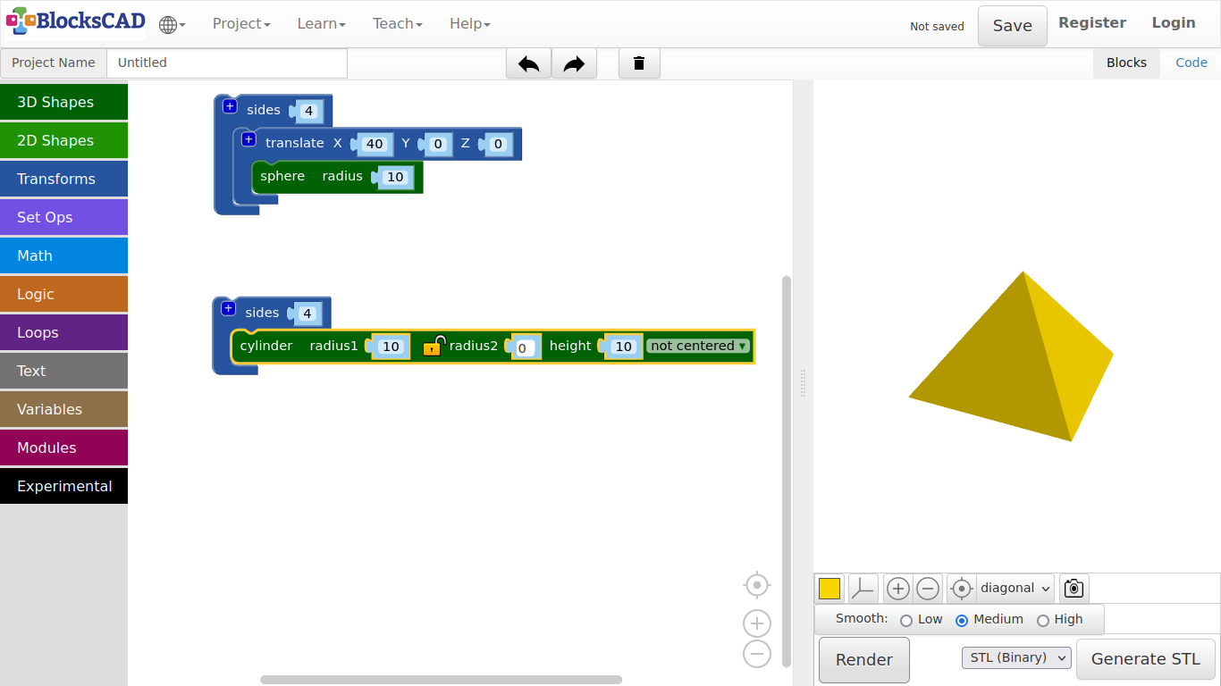
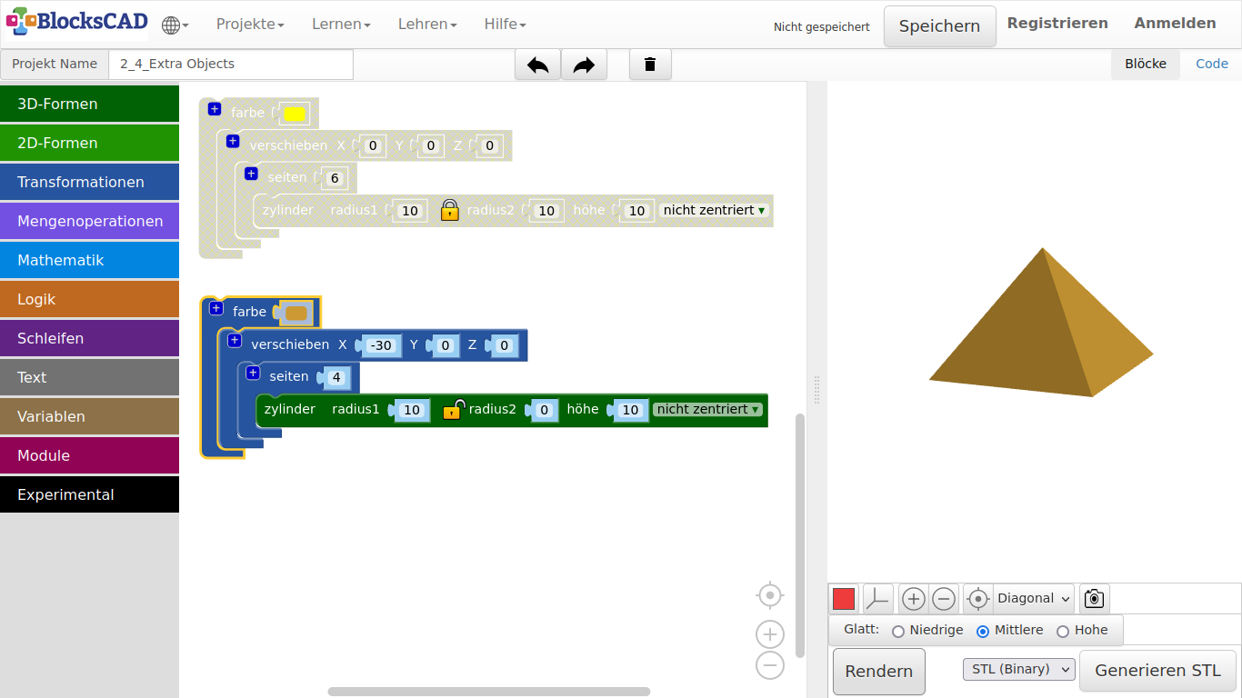
In geometry you call this shape an Octahedron.
-
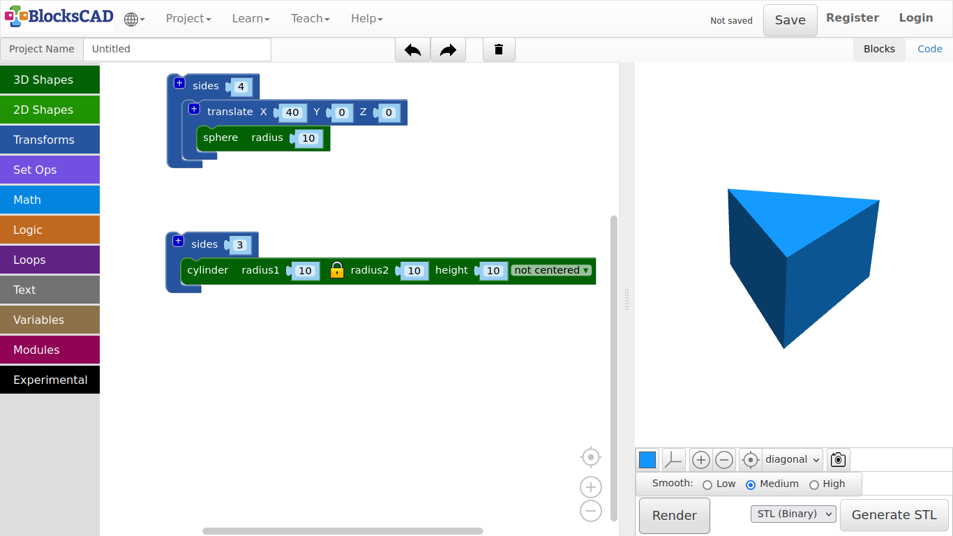
Now plug in the cylinder into the other sides, and change it to 3.
-
Press Render.
In geometry you call this shape an Triangular Prism.
-
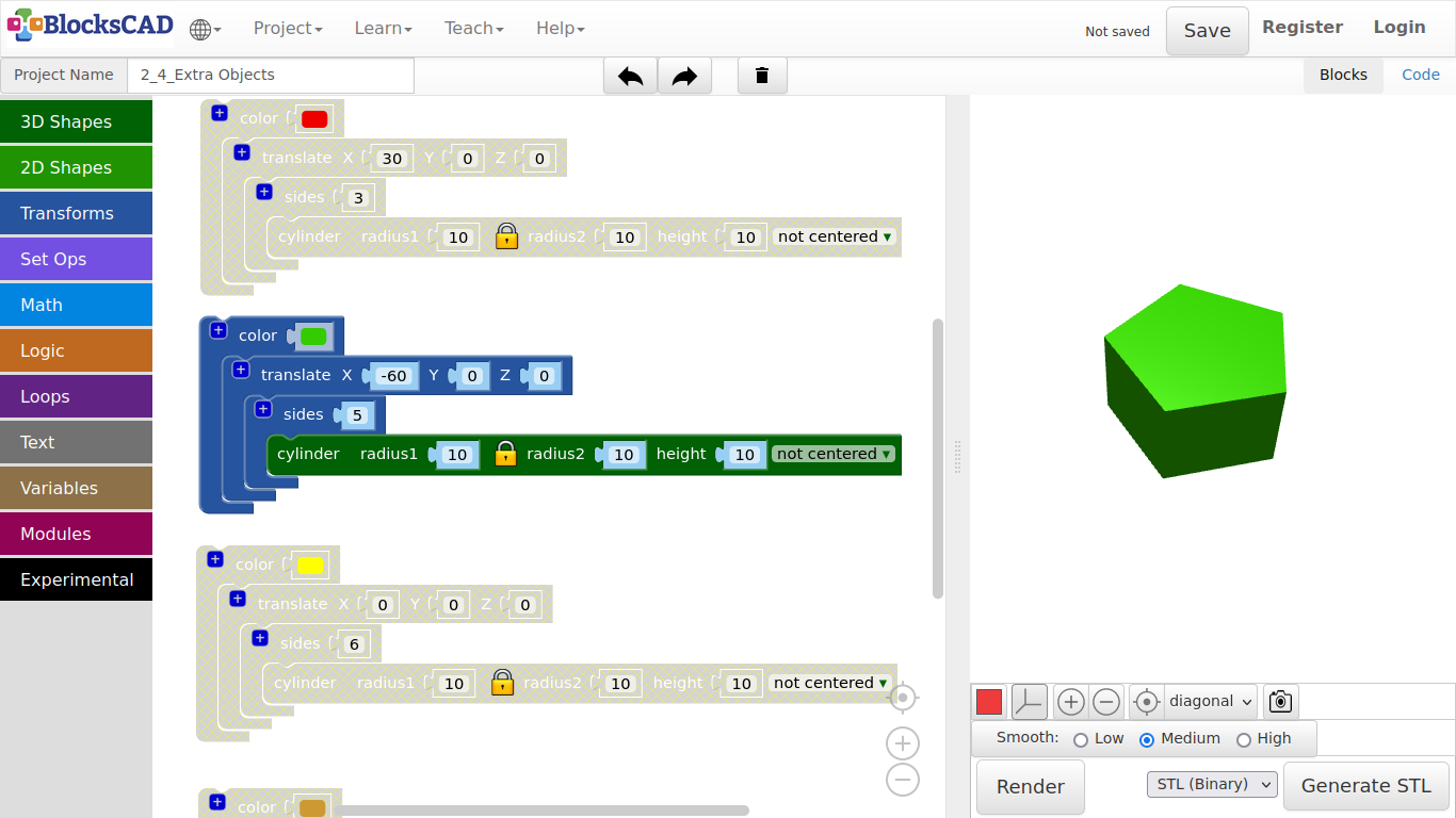
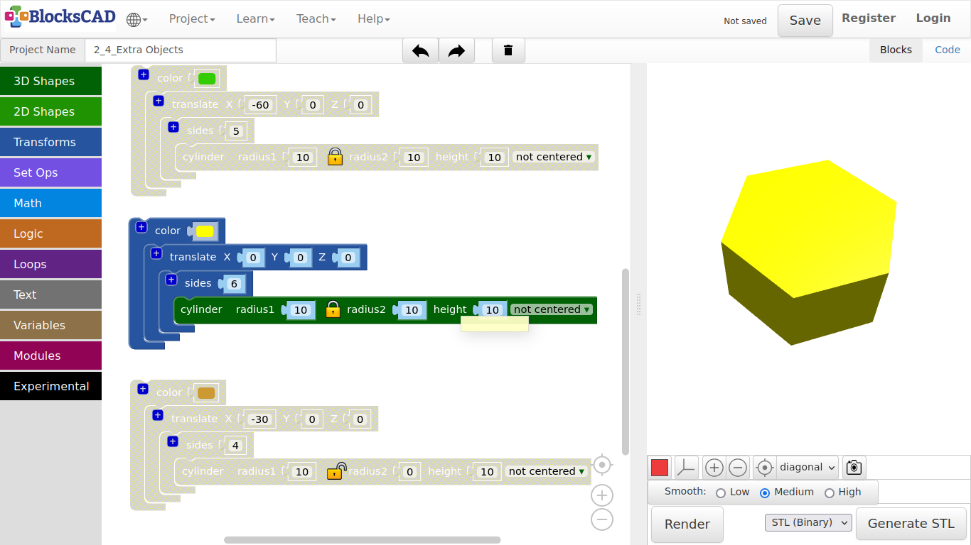
Change the value of sides to 5.
-
Press Render.
In geometry you call this shape an Pentagonal Prism.
-
Change the value of sides to 7.
-
Press Render.
In geometry you call this shape an Hexagonal Prism.
-
Now click on the Lock icon of the cylinder block and change radius2 to 0.
-
Change the sides value to 4.
-
Press Render.
In geometry you call this shape a Pyramid.
-
Name your project and save under Project >> Save Blocks to your computer.
-
Reopen your cup project under Project >> Load Blocks from your computer.
Exercise:
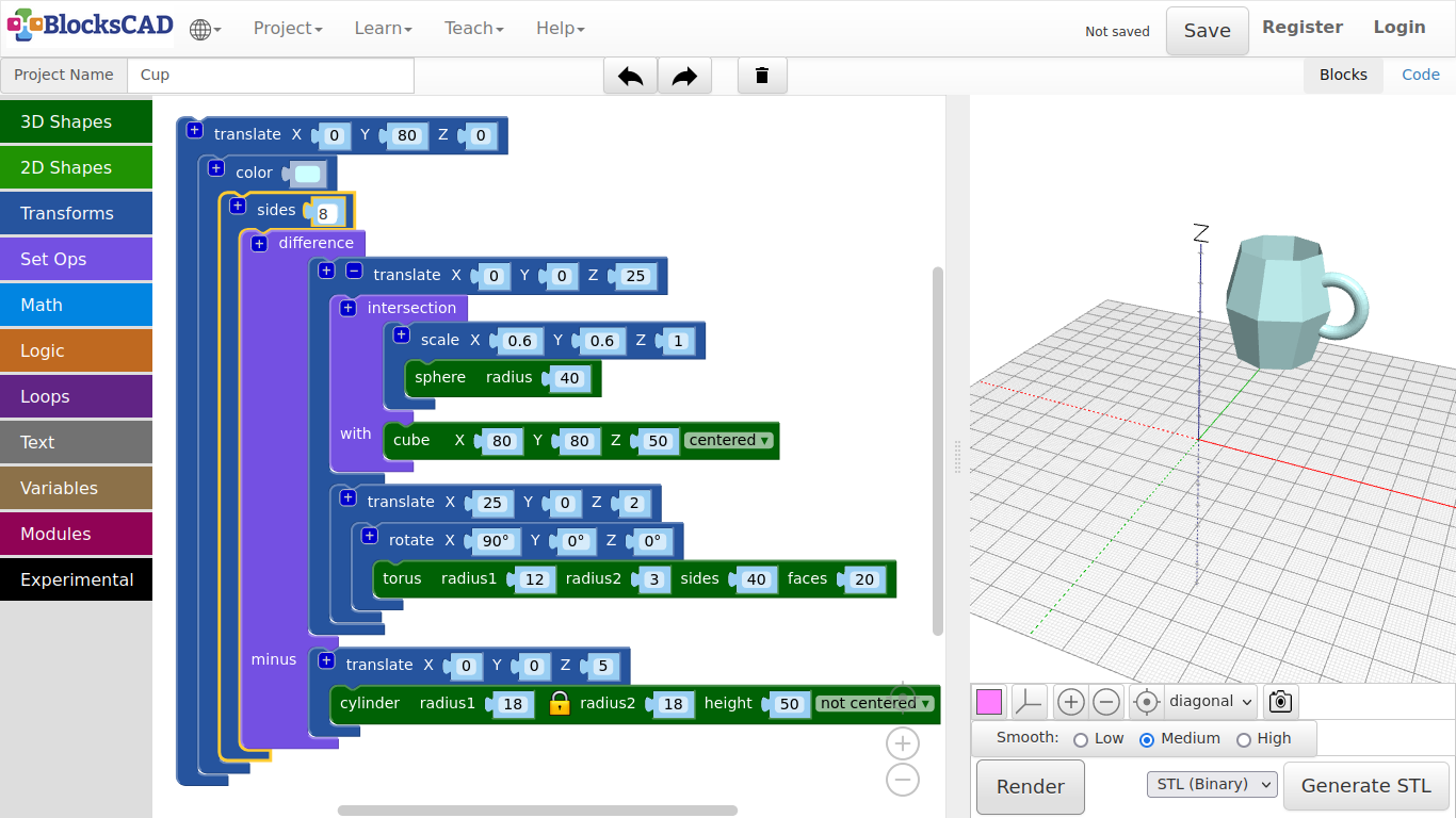
Create a similar object, e.g. a plate, a different cups, a bowl or other items. You can use the sides block to get different looks.
Tips:
- Use a translate block to move your cup aside.
- The rendering time will increase the more sides or polygons you have in the scene. To speed up the rendering reduce "sides" in this tutorial.
- What if you do not need the cup, but you want to keep it on your workspace as reference? Just click the RMB or use your 2 finger touch to open the Pop-up menu, then select "Disable Block".
- You can reverse it the same. It will show "Enable Block".


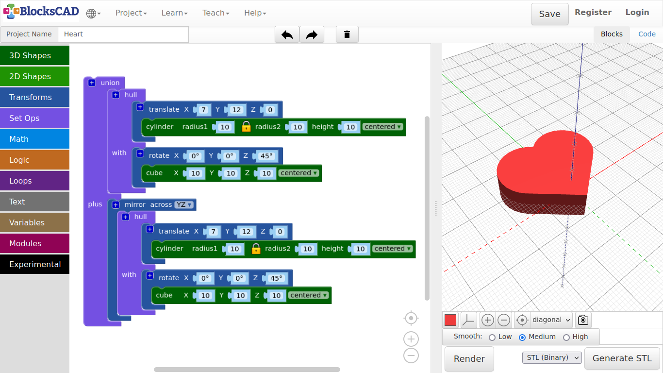
3.5. Heart

In this tutorial you will learn 3 new blocks: union, hull, and mirror. Lets get started!
-
Start wit a new project by pressing Projects >> New.
-
Drag and drop one cube block and one cylinder block from 3D Shapes, one translate block and one rotate block from Transforms, and one hull block from Set Ops onto your workspace.
-
Change the values of the cube to X = 10, y = 10, z = 10, centered, and plug it into the rotate block.
-
Change the Z value of rotate to 45 degree, so the cube becomes the edge on the bottom of the heart.
-
Now change the values of the cylinder to radius1 = 10, height = 10, centered and plug it into the translate block.
-
Changing the translate values to X = 7, Y = 12, Z = 0.
-
Now plug both blocks cube with rotate, and cylinder with translate into the hull block.
-
Press Render.
But this is only the half of the heart. How are we going to add the second part?
-
Drag and drop one mirror across from Transforms, and one union block from Set Ops.
-
Change in mirror across the value from XY to YZ.
-
Click onto the hull block, open the Pop-up menu, and press Duplicate.
-
Then plug the duplicate into the mirror block.
-
Now plug both of the main blocks into union.
-
Press Render
There you have a full heart!
- Name your project and save it.
3.6. Key chain
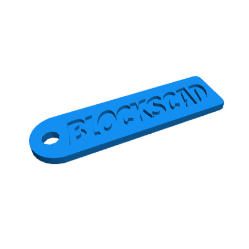
First, we will create the basic plate
-
Drag and drop three cylinder blocks from 3D Shapes, three translate blocks from Transforms, and one hull from Set Ops.
-
Change the values of the first cylinder to radius = 10, and height = 2, centered.
-
Plug it into one translate and change the X value to -30.
-
Change the values of the second and third cylinder to radius1 = 2, height = 2, centered.
-
Plug the second cylinder into translate, and change the X value to 30, and the Y value to 8.
-
Plug the third cylinder into the last translate, and change the X value to 30, and Y value to -8.
-
Press Render.
You should see one big disk on one side, and 2 small knobs at the other hand. We want to create one shape from those three objects.
-
Click on the + symbol on hull, and plug all three translate blocks with each cylinder into hull.
-
Press Render.
See, this is the basic plate!
Now let us add a hole, so we can hook it onto our key ring.
-
Drag and drop one cylinder from 3D Shapes, one translate from Transforms, and one difference from Set Ops.
-
The values for the cylinder are radius1 = 3, height = 3, centered.
-
Plug the cylinder into the translate block, and change the values there to X = -33, Y = 0, Z = 3.
-
Now plug the translate block with the hull block that contains the other three cylinder into the first position of difference.
-
Then plug in the translate module with the cylinder in the second section of difference named minus.
-
Press Render.
Now the keychain plate is finished!
Now you can add your graphics or names to it. Lets continue with a name.
- Drag and drop one translate from Transforms, and one 3D text from Text onto your workspace.
In order to cut the name into the plate, we need to add it to difference.
-
Press the + symbol on difference.
-
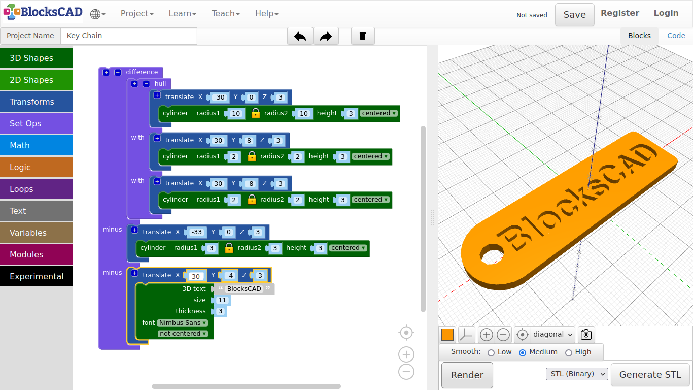
Change the values of 3D text as follow 3D text: BlocksCAD, size: 11, thickness: 3, font: Nimbus Sans.
-
Plug the 3D text block into translate and change those values to X = -30, Y = -4, Z = 3.
-
Then plug translate with the 3D text block into the third section of difference named minus.
-
Press Render.
-
Name your project and save it.
Lets use the heart we modeled previously to create a 2nd keychain.
-
Reopen the keychain project (if you closed it).
-
Rename it to IHeartU.
-
Unplug the last translate with the 3D text block by dragging it aside onto your workspace.
-
Drag and drop one union block from Set Ops, one translate and one scale from Transforms.
-
Plug union into the third section of difference named minus.
-
Now drag your translate with the 3D text block into the first section of union.
-
Change the values of this translate to X = -15, Y = -5, Z = 0*.
-
Change the values of 3D text to 3D text: I U, size: 14, thickness: 10, font: Roboto.
-
Press Render.
There are 6 empty spaces between I and U in the text. We want to match the heart between I and U.
-
Plug scale into the remaining translate on your workspace.
-
Change the values of scale to X = 0.4, Y = 0.4, Z = 0.3.
-
Now change the values of translate to X = 0, Y = -3, Z = 3.
-
Drag translate with the scale block into the second section of union named plus.
Now lets import your heart project!
- Go to Projects >> Import Blocks into Current Project, select your heart project file and press Open.
You might need to zoom out to see the imported block!
-
Drag the block into scale.
-
Press Render.
Your keychain should look like the one in the picture below.
- Save your project.
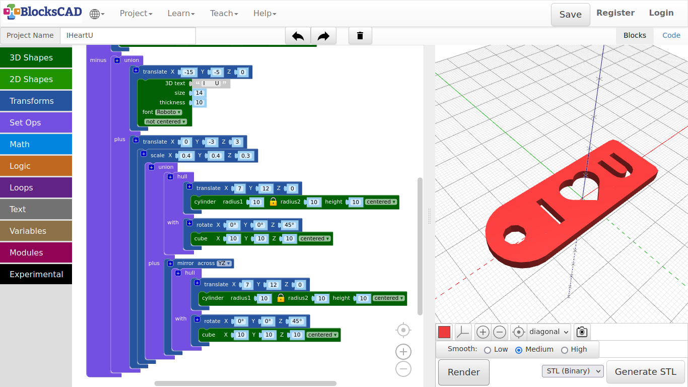
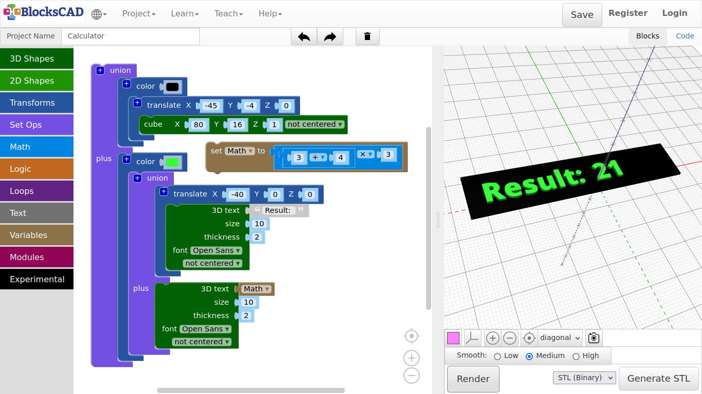
3.7. Calculator
Lets create a little calculator in BlocksCAD. You will be able to use all blocks in the math section put together math homework. Well a real calculator might be easier, but you can not make a model out of your result.
First we build a display background!
-
Drag n drop one cube from 3D Shapes, one translate and color from Transforms, and one union from Set Ops.
-
Change the value of cube to X = 80, Y = 16, Z = 1.
-
Then plug cube into translate.
-
Change the values of translate to X = -45, Y = -4, Z = 0.
-
Now plug translate with cube into color,and change the color.
-
Press Render.
You should see a small box that looks like a display. Now lets put the text "Result: " on top!
-
Drag and drop one 3D text from Text, one translate and one block color from Transforms, and one union from Set Ops.
-
Change the values of 3D text as follow: 3D text: Result: , size: 10, thickness: 2, font = Open Sans, and plug it into translate.
-
Change the values of translate to X = -40, Y = 0, Z = 0.
-
Drag translate with 3D text into the first section of union.
-
Now drag this block union into color. Change the color.
-
Press Render.
The blank calculator unit is ready! Now we need the actual math part!
-
Drag and drop one 3D text block from Text, two 1 + 1 blocks from Math, and one set item to block from Variables.
-
Plug one 1 + 1 into the first number place of the second 1 + 1 block, which results in 1 + 1 + 1.
You can change number, operators or replace blocks with other blocks from Math. This depends on what you want to calculate!
-
Now drag this math block part into set item to block.
-
Click on item and choose from the Drop-down menu Rename.
-
Rename it to Math.
-
Now take the 3D text block and plug it into the second part of union named plus.
-
Drag n drop the new Math block under Variables onto the first value of 3D text, where the text suppose to go.
Each time you create a new variable, BlocksCAD generates its own blocks "set YOUR_NAME to" and "YOUR_NAME". This is very important for parametric design.
We actually will now do our first parametric design.
-
Change the rest of values of 3D text as follows size: 10, thickness: 2, font: Open Sans.
-
Press Render.
You should see 3 now as the result of 1 + 1 + 1. Play a bit around with the numbers and operators to see the results, after you rendered the preview.
And this is what parametric design all about. You can change the numbers in the variable, and the program will adjust the new numbers.
Lets do another little example, so you understand parametric modeling a bit better.
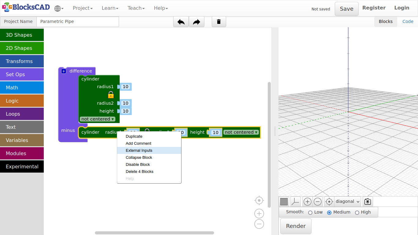
Lets create a pipe that we can change easy!
-
Start a new project.
-
Name it Parametric pipe.
-
Drag n drop two cylinder from 3D shapes, one difference from Set Ops to your workspace.
-
Plug in both cylinder into difference.
-
Use you right mouse button or finger touch to open the Pop-up window and choose External inputs.
This will change the way the block is displayed. As we use variables soon, it would become a very long block. This way, it will easier to work with.
-
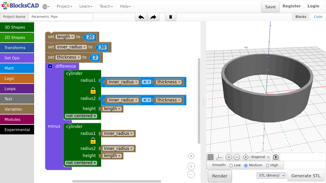
Drag and drop three set item to blocks from Variables, two 1 + 1 blocks and three 0 blocks from Math.
-
Plug in one 0 block in each set item to block.
-
Use the Drop-Down menu of each set item to, select New Variable ..., and use following names length, inner_radius, thickness.
-
Change the value in 0 of set length to to 20.
-
Change the value in 0 of set inner_radius to to 30.
-
Then change the value in 0 of set thickness to to 2.
-
Now plug in one 1 + 1 block into the cylinder for radius1 of the cylinder in the first section of difference.
-
In the same cylinder plug in the second 1 + 1 block for radius2.
-
Drag and drop four inner_radius blocks, two thickness blocks, and two length blocks from Variables onto your workspace.
-
Plug in one inner_radius block into each first position of 1 + 1 of radius1 and radius2 of the cylinder in the first section of difference.
-
Plug in the remaining two inner_radius blocks as radius1 and radius2 of the cylinder in the second section of difference named minus.
-
Plug in one thickness block into each second position of 1 + 1 of radius1 and radius2 of the cylinder in the first section of difference.
-
Finally, plug in one length block for the height value of each cylinder.
-
Press Render.
Now you create a fully parametric design for a pipe!
Change the values of length, inner_radius, and thickness, while pressing Render after the change to see the different outcomes.
3.8. Pavilion
Before we go and model the Pavilion, I will introduce you to the use of loops in modeling. Loops are essential in programming. The loop repeats a certain task till it the program reaches a specified condition.
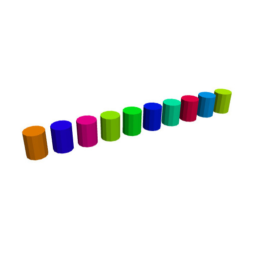
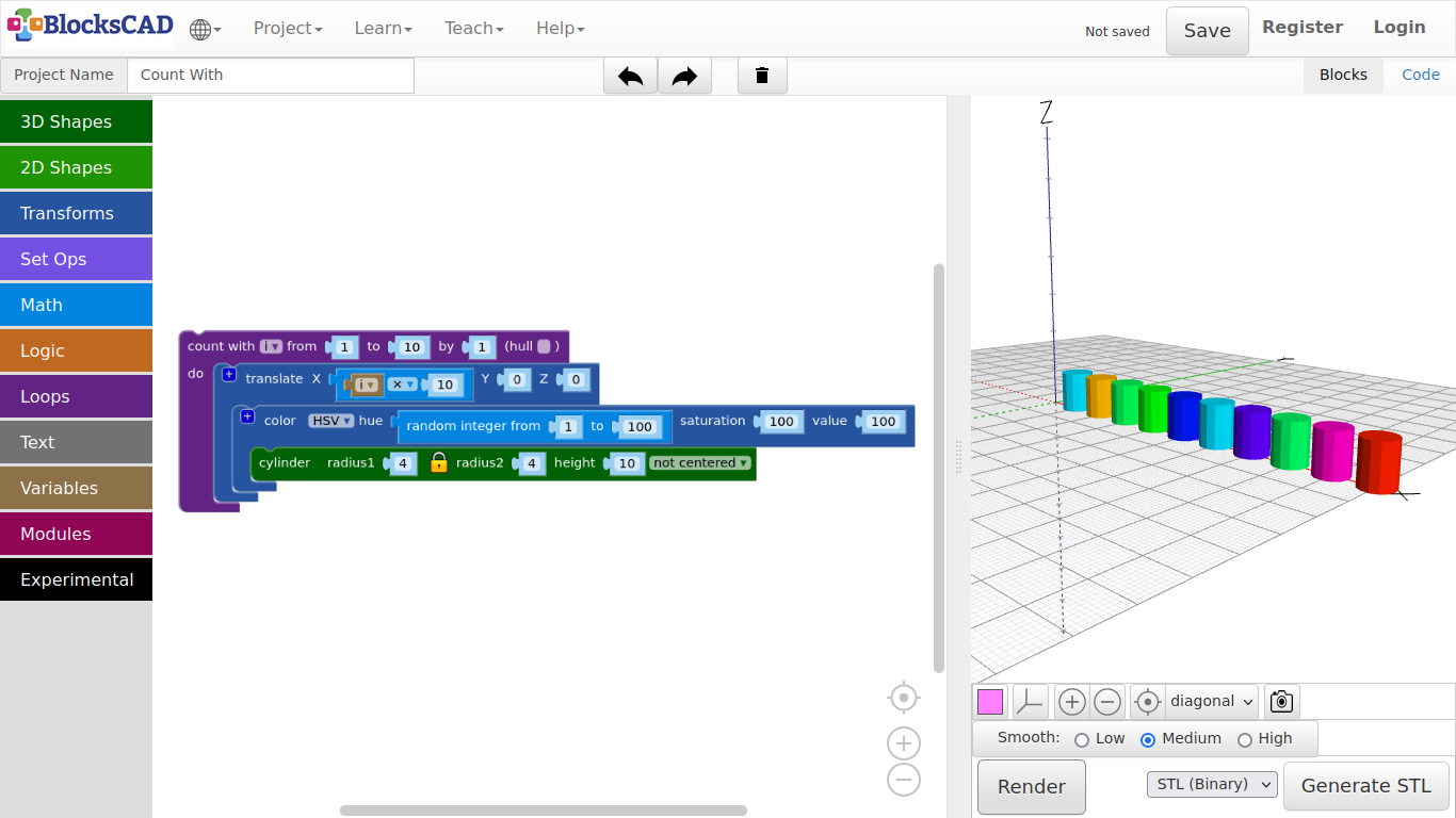
In the following example, we will create 10 cylinders positioned side by side through a loop.
-
Drag n drop one count with from Loops, one translate from Transforms, one 1 + 1 from Math, and cylinder from 3D Shapes onto your workspace.
-
Change the values of cylinder to radius1: 4 and height: 10, and plug it into translate.
-
Drag n drop i from Variables onto the workspace, then plug it into the first position of 1 + 1 instead of 1.
-
Change the + sign to x, and change the second 1 to 10.
-
Now plug the i x 10 block into X of translate.
-
Plug translate into count with.
-
Press Render.
The loop counts from 1 to 10 by 1. i is the variable, that contains the current number of the count. Each step the loop creates a cylinder and moves it along the x axis by 10. There are 10 cylinders with a distance of 10 mm along the x axis. Lets add some colors to the cylinder randomly!
-
Drag out cylinder out of translate.
-
Drag and drop one color HSV block from Transforms, and one random integer from Math onto the workspace.
-
Plug random integer into hue of the color HSV block, and plug this one into translate.
-
Now plug in the cylinder block into color HSV.
-
Press Render.
Every time you press Render, the cylinders will be recreated with different colors!
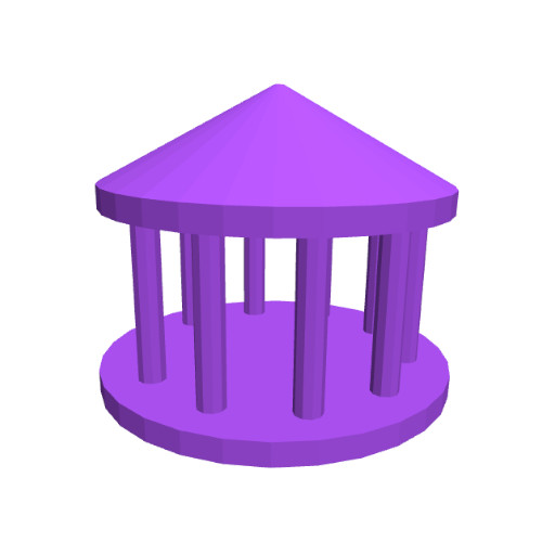
Now lets model a pavilion.
-
Drag n drop three cylinder from 3D Shapes, and two translate blocks from Transforms.
-
Change the value of the first cylinder to radius1 = 40, height = 5.
-
Press Render.
This is the foundation! Now lets build the roof with the other cylinders.
-
Change the values of the second cylinder to radius1 = 38, height = 5, and plug it into the first translate. Then change the values of this translate to X = 0, Y = 0, Z = 40.
-
Like in with the umbrella example, click on the lock symbol of the third cylinder to unlock the 2nd radius.
-
Change the values of this cylinder to radius1 = 38, radius2 = 1, and height = 20.
-
Then plug it into the second translate block and change its Z value to 45.
-
Press Render.
See! The empty space between the foundation and the roof are going to be filled with columns that circles around near the outer edge!
To avoid modeling of each column, we will use a loop, like in the starting example to create all of them at once. Each cycle of the loop will create one column, and apply a translation and rotation to it.
-
Drag and drop one cylinder from 3D Shape, one translate block and one rotate block from Transforms, one count with from Loops, and the just created block i in Variables.
-
Change the values of the cylinder to radius1 = 3, height = 40, and plug it into the translate module.
-
Then enter 30 as X value in the translate block.
-
Now we plug this into the rotate block, and use the variable block i as Z of rotation.
-
Press Render.
As you see, there is the first column!
i is a variable that represent a number. We want to build 10 columns, that is going to be positioned near the outer edge. To do this, we need to rotate it with each loop, so the 10 columns get distributed all around the outer edge.
We will do this with the “count with” block. It is already using “i”, so we do not need to change this. The counter will start with 1 and end with 360, which is one full turn. As we want to create 10 columns, we will increase the value “i” by 36 each loop.
-
Change the values of count with to from: 1 to: 360 by: 36.
-
Now plug in the rotate block with translate and the cylinder into the count with block.
-
Press Render.
Exercise:
Create a little model and multiply it with “count with”. You can use translate in all directions, or different rotations.
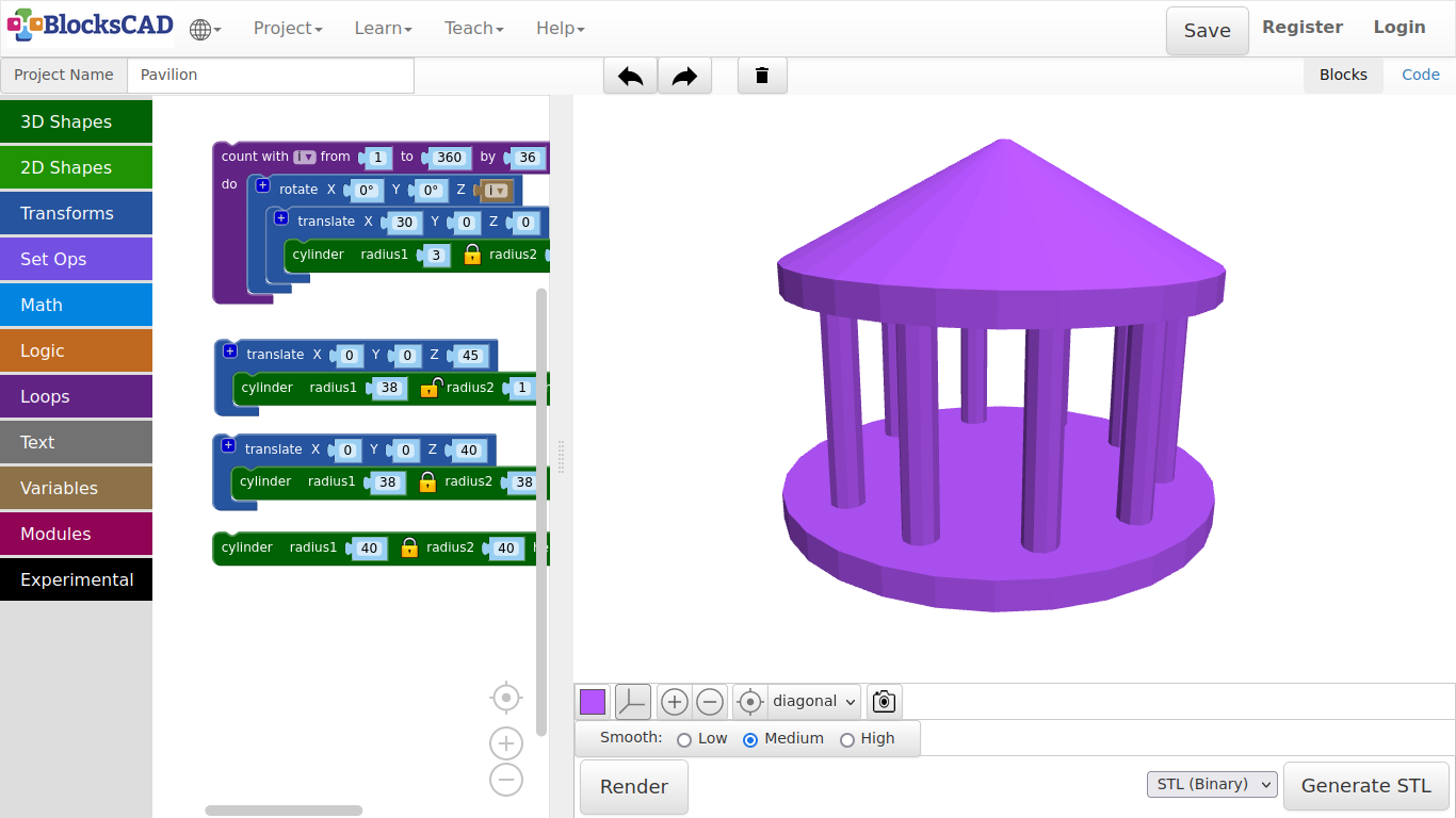
3.9. Pine tree
We will now create a tree, that can be later used to build a forest.
With this you will be introduced to the functionality of modules. Modules are like a block box, that contains many many blocks at once. This block box is then represented by a single block.
Lets build first the trunk, then the rest with the module we just learned about!
-
Drag n drop one cylinder from 3D Shapes, and one color from Transforms.
-
Change the value of the cylinder to radius1 = 2, height = 10.
-
Plug it into the color block, and change the color to brown.
-
Press Render.
Now lets do the tree top or pines in an easy form.
-
Drag and drop one cylinder from 3D Shape, one translate and one color from Transforms, one count with from Loops, one 1 + 1 block from Math, and the generated i block from Variables onto the workspace.
-
Change the value of cylinder to radius1 = 10, radius2 = 1, height = 10, then plug it into translate.
-
Add the i variable into the first position of the 1 + 1 block.
-
Change the operator symbol + to x, and the second number to 10.
-
Now plug it into the Z value of translate, so with each loop the next object created will move up by 10.
-
Now we plug all into the count with block.
We want to create 3 parts, so we will do 3 loops.
-
Change the values count with to from: 1 to: 3 by: 1.
-
Next plug the whole block you just created into the color block, and change color to green.
-
Press Render.
You should see a nice pine tree now!
But it is just one tree. What is to do to use the same tree many times, but not duplicate the tree each time for a new one.
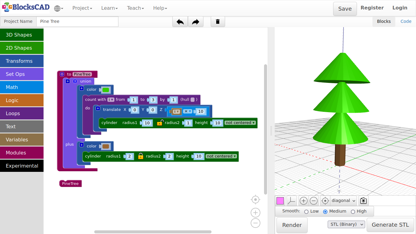
All blocks you can choose in BlocksCAD are actually modules, that you used to create your objects. However, you can create your own modules to create customized blocks.
That is why I show you this with the pine tree. We will build a forest, that will use the pine tree module as block.
-
Drag and drop one To do something block from Modules, and one union block from Set Ops onto your workspace.
-
Plug the trunk color block inclusive all embedded blocks, and the tree top color block with all blocks into the union block.
-
Change the To do something blocks name do something into Pine Tree, and plug the union block into it.
-
Press Render.
What!? Nothing to see? That is right, as the Pine Tree is a module now.
As all other blocks, you will need to drag and drop it first onto your workspace.
-
Drag and drop Pine Tree from Modules onto your workspace.
-
Press Render.
The tree should re-emerged again.
Save this project and name it, so you can use it in our next project.
-
Now delete the Pine Tree block you just dragged in.
-
Name the project after the name of your module Pine Tree and save it.
Exercise:
Create similar modules, e.g. flowers, stones, or similar things you find in a forest. Save each separately. Do not forget to erase the module representing block with the module name, before saving.
Tip: Create first the object without plugging it into "To do something" block. Only plug it in, before you finished as last step before saving!
4.1. Finger Ring
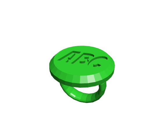
Our first object, that you can print is going to be a finger ring. You can use ruler to measure your finger diameter. It is even easier, if you have got a ring already.
Lets get started!
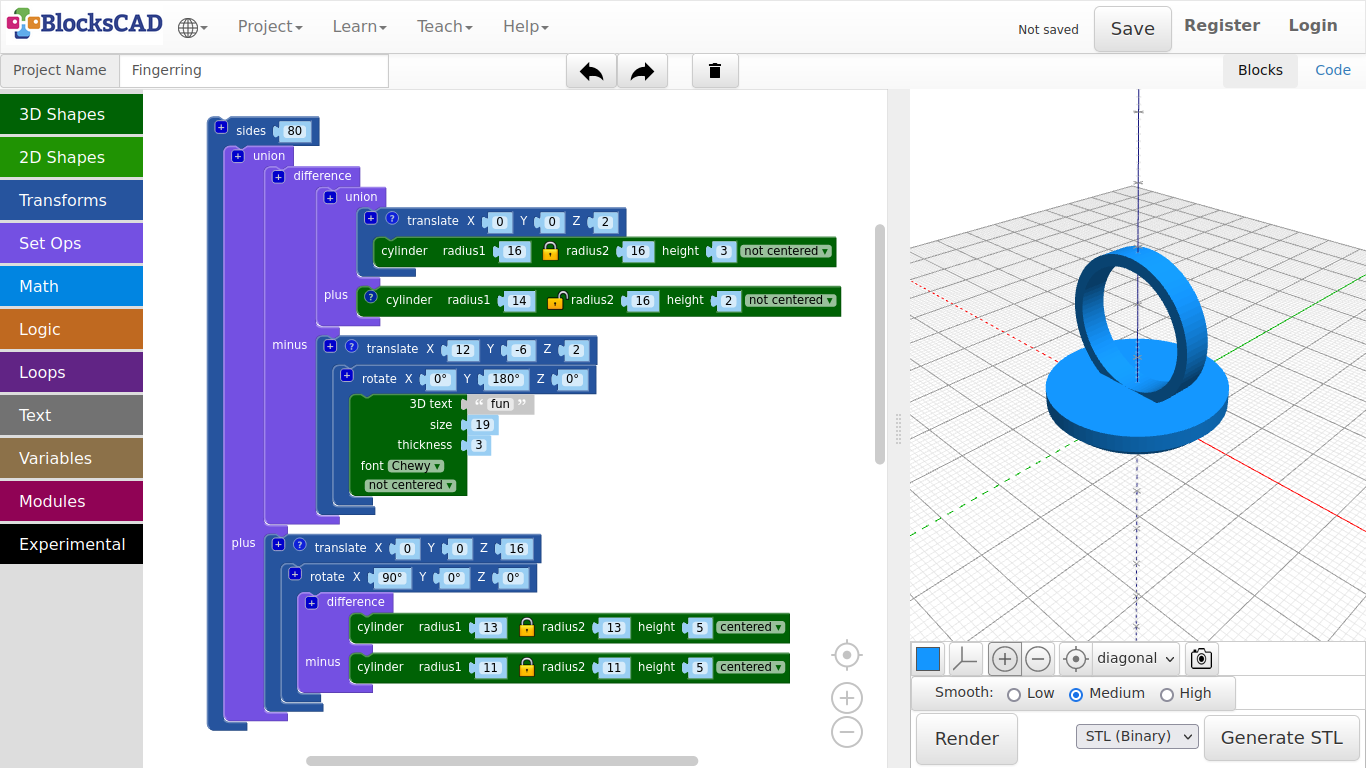
- As always, lets create a new project and name it Fingerring.
First, lets create be ring base!
-
Drag and drop two cylinders from 3D Shapes, one translate from Transforms, and one union from Set Ops onto your workspace.
-
Plug one cylinder into translate.
-
Change the values of cylinder to radius1: 16, height: 3.
-
Change the values of translate to X: 0, Y: 0, Z: 2.
-
Now plug the translate block with the embedded cylinder into the first section of union.
-
Plug the second cylinder into the second section of union named plus.
-
Click on the lock icon of this cylinder to disconnect radius2 from radius1.
-
Change the values of this cylinder to radius1: 14, radius2: 16, height: 2.
-
Press Render.
You should now see the base of the ring. Lets carve out the word "fun". But it also can be a graphic like the heart we modeled.
-
Drag and drop one 3D text from Text, one translate block and one rotate block from Transforms, and one difference block from Set Ops.
-
Plug in the 3D text block into rotate.
-
Change the values of 3D text to text: fun, size: 19, font: Chewy, thickness: 3.
As you might already recognized, the base of the ring is upside down. This is because of the printing guide. Start with the side, that has the biggest flat surface.
Therefore, we need to turn the text 180 degrees.
-
Change the Y value of rotate to 180 degrees.
-
To get the text into the center of the base change the values of the translate block to X: 12, Y: -6, Z: 2.
-
Press Render.
It is fun on the base!
Now lets create the actual ring. This is very similar to the previous parametric pipe example.
-
Drag and drop two cylinder from 3D Shapes, one translate and one rotate from Transforms, and one difference from Set Ops onto your workspace.
-
Plug in a cylinder into the first section of difference, and change its value to radius1: 13, height: 5.
-
Plug in the second cylinder into the second section of difference named minus, and change its values to radius: 11, height: 3.
-
Plug difference into rotate and change the value of X to 90.
-
Now move rotate into translate and change the Z value of translate to 16. This is the height of the rotated ring.
-
Press Render.
You should see the ring now with base and carved text. However, the edges are still rough.
Lets add smoothness to it!
-
Drag and drop one sides block from Transforms, and one union block from Set Ops onto your workspace.
-
Plug in the base part into the first section of union, then the ring part into the second section named plus.
-
Now drag the entire union block into sides. Change the value to 80.
-
Press Render.
-
Name your project and save it to your computer.
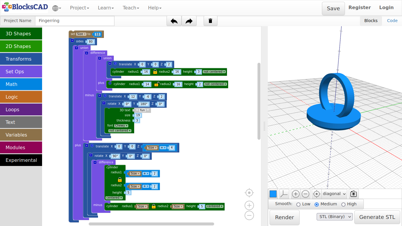
Exercise:
- Change the ring inner radius to the variable size and change the outer ring accordingly. This must be connected to the height of the ring as well, which is "Z" of "translate".
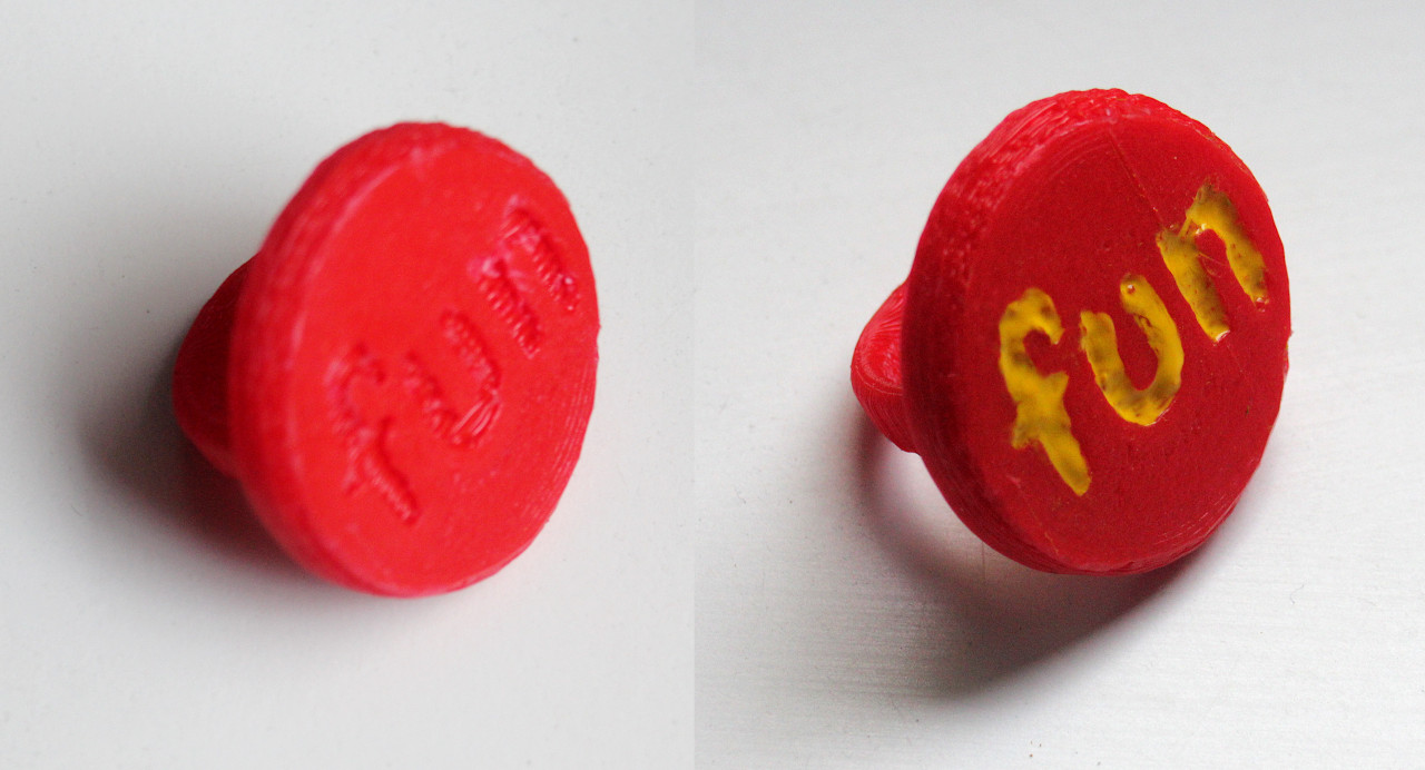
- Change the text, font size and font in 3D Text, adjust translate() of the text, so it it is in the center of your button. You might want to try other shapes, or mix of shapes instead of letters.
A printed example
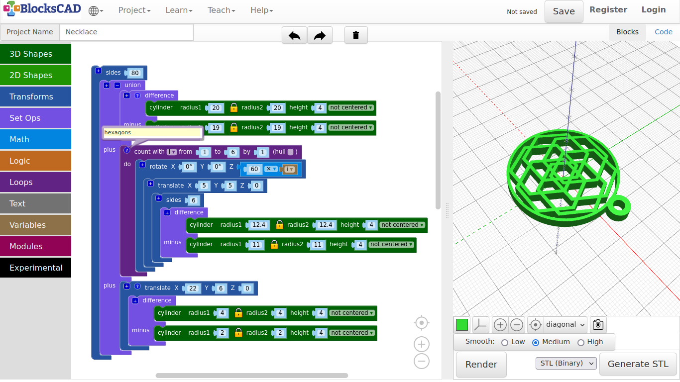
4.2. Necklace
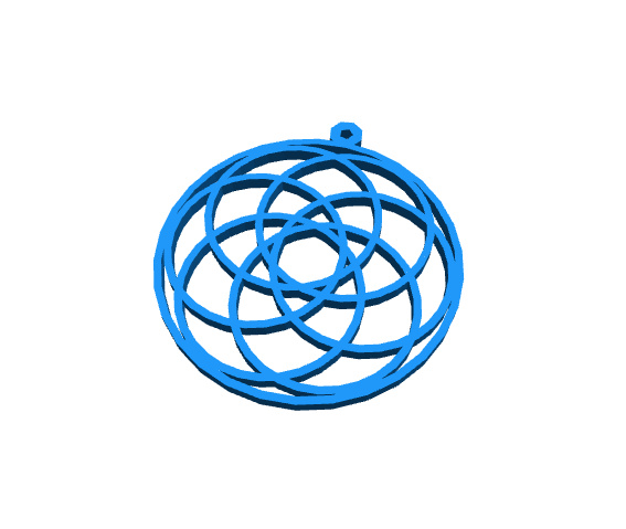
In this examples we will use loop again to create nice geometric patterns, that we will use to create necklaces.
-
First, lets create a new project.
-
Drag and drop two cylinder from 3D Shapes, and one difference block from Set Ops onto your workspace.
-
Plug in both cylinder into difference.
-
Change the values of the first cylinder to radius: 20, height: 4, and the values of the cylinder below to radius: 19, height: 4.
-
Press Render.
You now should see a nice ring. Well, not really, however we will smooth the edges later. Now lets add shapes within this outer ring! We start with rings.
-
Repeat 2. and 3.
-
Now change the values of the first cylinder to radius: 12, height: 4, and the values of the second cylinder to radius: 11, height: 4.
-
Press Render.
You should see a smaller ring within the bigger ring.
-
Drag and drop one translate and one rotate from Transforms onto your workspace.
-
Plug in the difference block into translate, and change the X and Y value of translate both to 5.
You should see the ring lining up with the outer ring, while set a bit off.
-
Now plug this entire block into rotate.
-
Change the Z value with different numbers, press Render each time.
The inner ring should now "roll" around the outer ring. This is what we want to do, but moving around each ring to a different position.
- Drag and drop a count with block from Loops, a 1 + 1 block from Math, and the new variable i generated in Variables onto your workspace.
We will do something similar, that we did by building the pavilion.
So what do we want to do? We want to create one ring and rotate each around the center. For 6 rings, each ring needs to rotate: 360 / 6 = 60 degrees.
-
Plug in the i variable into the second position of the 1 + 1 block, and change the values to make it look like 60 x i.
-
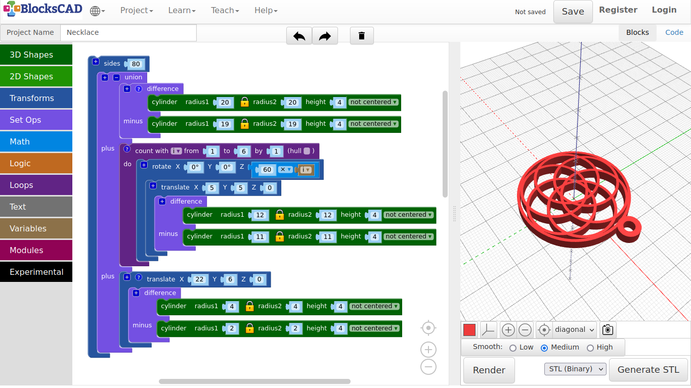
Now plug the entire block rotate into count with, and change the values as follows >> from: 1 to: 6 by: 1.
-
Press Render.
See!? A nice flowery pattern.
But how do we attach it to the chain? We need another ring on top of the outer ring.
-
Go to any of the difference, select it, then use your right mouse button or hold your finger on it. Choose Duplicate from the Pop-up menu options.
-
Move it down to the bottom of the entire blocks.
-
Drag and drop in a translate block from Transforms. Change the values to X: 22, Y: 6, Z: 0.
-
Then plug the duplicated difference block into translate. Change the values of the first cylinder to radius1: 4, height: 4, and the values of the second cylinder to radius: 2, height: 4.
-
Press Render.
You should see now a ring on the outer edge of the big ring.
Now lets smoothed the edges again!
-
Drag and drop one union block from Set Ops, and one sides from Transforms onto your workspace.
-
Press the + icon on the union block to add one more slot.
-
Plug all three block entities difference, count with, and translate one in each slot of union.
-
Then plug this union block into sides, and change the number to 80.
-
Press Render.
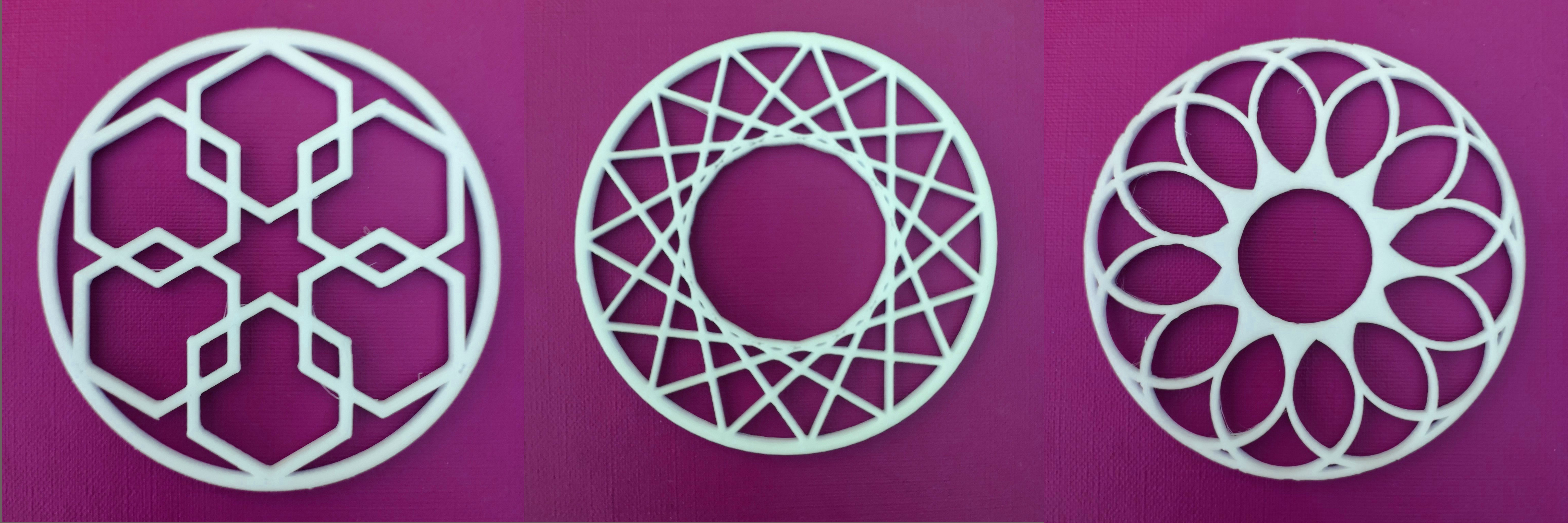
Finished!
Ready to print. It should looks similar to the image below.
- Like always, name and save your project.
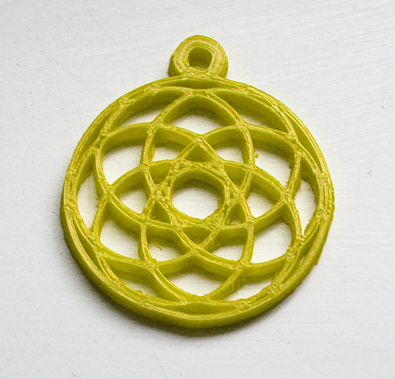
Printed example:
Exercise:
Duplicate your “Count with” block, and disable the original block via RMB/Finger touch “Disable block”. Move the duplicated version below and start experimenting. Try different shapes.
Tip:
- Use sides() between translate() and difference() with 3, 4, 6 in order to create different shapes easy. Change the values in translate() to get different results.
- Increase or reduce "to" in "count with", and degrees in "rotate" beneath, to change to outcome of the patterns.
- Again, reduce the number of entire sides (from 80 down to 20 or even lower), when you experiment with shapes. Otherwise, it takes more time to render, and you have to wait longer. Once you are satisfied with your design, increase the sides number.
Squares example:
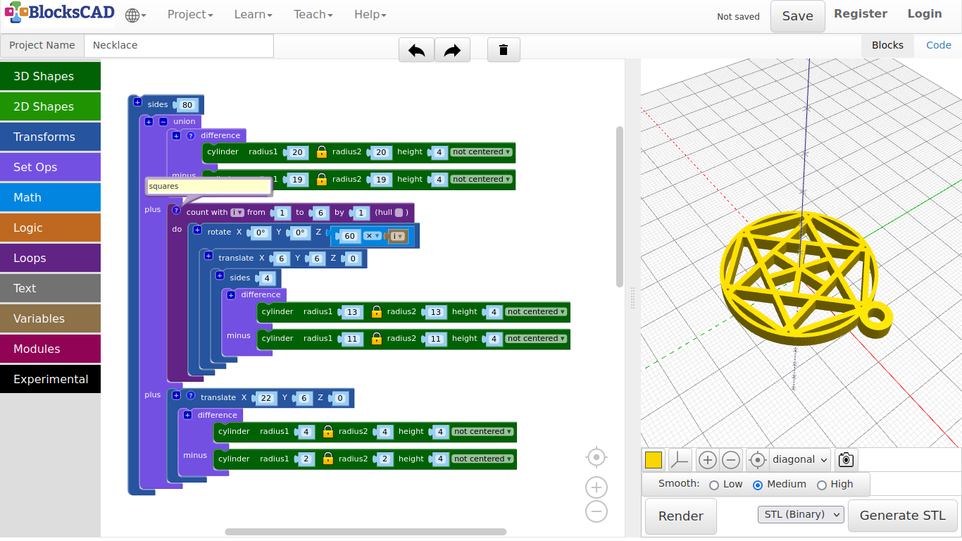
Hexagons example:
Exercise
Can you make these?!
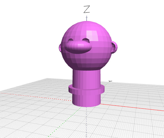
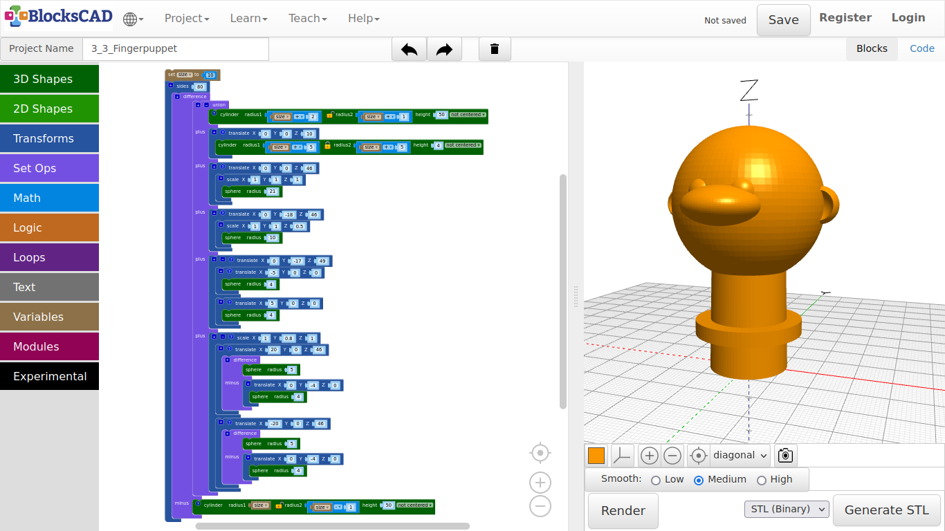
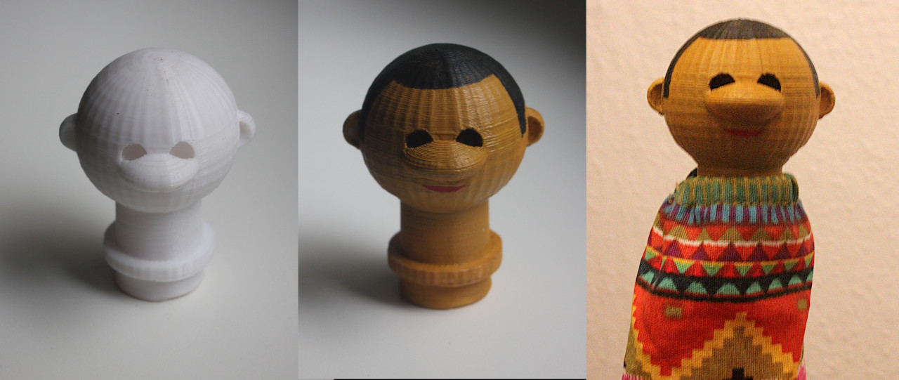
4.3. Finger Puppet
First, we need to measure our index finger to know, what each of us need to put into the values later. For that use your ruler and write down the diameter of your index finger just above the second joint. Measure from front and side and take the bigger number.
If there is no ruler around right now, just use the basic values in this tutorial. We are going to model the neck parametric, so you can change it easier later.
-
First, create a new project.
-
Drag and drop three cylinder from 3D Shapes, one difference and one union block from Set Ops, and one translate from Transforms.
-
Plug in union into the first section of difference.
-
Then plug in the translate block into the second section of union named plus, and change the values to X: 0, Y: 0, Z: 10.
-
Now plug in one cylinder into the first section of union, the second cylinder in the translate block in the second section of union, and one cylinder in the second section of difference named minus.
Now lets prepare the neck of your finger puppet to be parametric!
-
Drag and drop one set item to from Variables, one 0 block and one 1 + 1 block from Math onto your workplace.
-
Click on item of the set item to and rename it to size.
-
Now drag in the new block named size from Variables onto your workspace.
-
Plug in 0 into set size to, and change it to 10.
-
Now duplicate the size block once by right clicking or holding your finger on the block till the Pop-up menu opens, so you can select Duplicate.
-
Take this duplicate size block and plug it into radius1 of cylinder in the second section of difference called minus.
-
Click on the Lock icon in the same cylinder.
-
Then plug in the remaining size block into 1 + 1 as first number. Change the rest so it looks like size - 1.
-
Now plug size - 1 into radius2 of cylinder and change height to 50.
-
Select the size - 1 in radius2 of the cylinder block.
-
Duplicate it four times, and plug those 4 for each radius1 and radius2 of the remaining two cylinder.
-
Click on the Lock icon of the cylinder in the first section of union. Change to values till it looks like radius1: size + 2, radius2: size + 1, height: 50.
-
Now change the values of the cylinder of the second section of union named plus to look like radius1: size + 5, radius2: size + 5, height: 4.
-
Press Render.
You should have a cylinder looking similar like the pipe example, except there is an extra collar cylinder. Try a different number in "size", and press "Render" to see the changes. This is where you finger will be. The collar is the part, that holds your puppet clothing in place. Now we will continue with the head. Follow the instructions, but you can start from here again, if you would like to create your own head.
- Press the + icon of union four time to create four extra slots, which will result in six slots in total.
First and second is already used by the neck and the collar. The third is for the head shape, the fourth for the nose, the fifth for the eyes, and the sixth for the ears.
Lets start with the head!
-
Drag and drop one sphere from 3D Shapes, one translate block and one scale block from Transforms onto your workspace.
-
Change number in sphere to 21, and plug it into scale.
-
Keep scale at is 1, 1, 1, and plug it into translate.
-
Change the values of translate to X: 0, Y: 0, Z: 46 and plug it into the third slot of union.
-
Press Render.
Super....Charlie Browns soccer ball head! Next the nose!
-
Select translate of the head sphere, and click the right mouse button or hold your finger till the Pop-up menu appears.
-
Choose Duplicate, and plug the whole block into the fourth slot of union.
-
Now change the values of sphere to 21, of translate to X: 0, Y: -18, Z: 46, and of scale to X: 1, Y: 1, Z: 0.5.
-
This translate block with both duplicates goes into the fourth slot of union.
-
Press Render.
Do not be so nosy...the nose is not the only thing! Lets carry on with the eyes!
-
Drag and drop two sphere from 3D Shapes, and three translate from Transforms onto your workspace.
-
Now plug each sphere in one translate, then both translate blocks with their sphere into the remaining translate.
-
Press + to add one slot to the main translate, so both translate fit in.
-
Change the value of both sphere to 4.
-
Then change X value of both translate above to 5 and -5 accordingly.
-
Change the values of the main translate to X: 0, Y: -17, Z: 49.
-
This translate block goes now into the fifth slot of union.
-
Press Render.
Both eyes should appear. The spheres are identical, except translate is positive 5 and negative 5 for each eye.
Encapsulating blocks is very useful so you can keep it in relation with each other, while being able to use these block as a group.
In this example we can now move around the both eyes with the main "translate" block.
Lets continue with the ears!
-
Drag and drop two spheres blocks from 3D Shapes, two translate block and one scale block from Transforms, and one difference from Set Ops onto your workspace.
-
Plug one sphere into one translate block, and change the value to 4.
-
Take this translate block with the sphere and drag it into the second section of difference named minus. Change the value Y of translate to -4.
-
Now plug in the second sphere into the first section of difference, and change the value to 5.
-
Plug this difference block now into the remaining translate block, and change the values of translate to X:20, Y:0, Z:46.
-
Select this translate block and duplicate it.
-
In the duplicate, only change the values of the translate block on top to X:-20, Y:0, Z:46.
-
Now plug both of these translate blocks with their content into scale and change the Y value of scale to 0.8.
-
The scale block finally can go into the sixth slot of union.
-
Press Render.
Ok, so far so good!
But all is a little minecraft. Lets smooth it up a little again!
What block did we used last time?
-
Drag and drop one sides from Transforms into the scene.
-
Take now the entire difference block and plug it into sides.
-
Change its value to 80.
You can use a different number, if you like. Remember, the higher the number, the more squares and triangles in the scene, the longer it will take to render.
-
Press Render.
-
Name the project and save it.
Exercise:
Create your own head. Start by naming the project differently, so you keep everything we did in this project so far.
Tip:
- Draw a doodle of a head first, so you can see in front of you, what you want to create.
- Create only one side of eyes and ears first, then duplicate those parts later on.

4.4. Shoe Tag
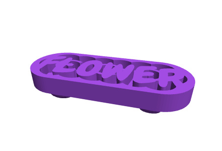
The shoe tag has holes to thread your shoe laces. So you can wear it with your shoes.
-
As usually, lets start with a new project.
-
Name it Shoe Tag.
Like the finger ring, we will create the base first!
Also this time, we will build it upside down, as it is better to print it that way. Lets start with the base. We are going to use "hull", that creates an objects from all objects within this block.
-
Drag and drop one cylinder from 3D Shapes, one translate from Transforms, and one hull block from Set Ops onto your workspace.
-
Click the lock icon on cylinder to unlock the connection between radius1 and radius2, and change the values to radius1: 11, radius2: 12, height: 7.
-
Now plug the cylinder into the translate block, and change its X value to -18.
-
Select the translate block and duplicate it.
-
Plug in both translate blocks into hull.
-
Press Render.
"hull" combined both cylinders to one element. The different radius gives it a little slop. Now we will cut out a part to make space for a word.
-
Drag and drop one difference block from Set Ops onto your workspace.
-
Select the hull block group and duplicate it.
-
Plug both hull groups into difference.
-
Change the values of cylinder in the second section of difference named minus to radius1: 9, radius2: 9, height: 3.
-
Press Render.
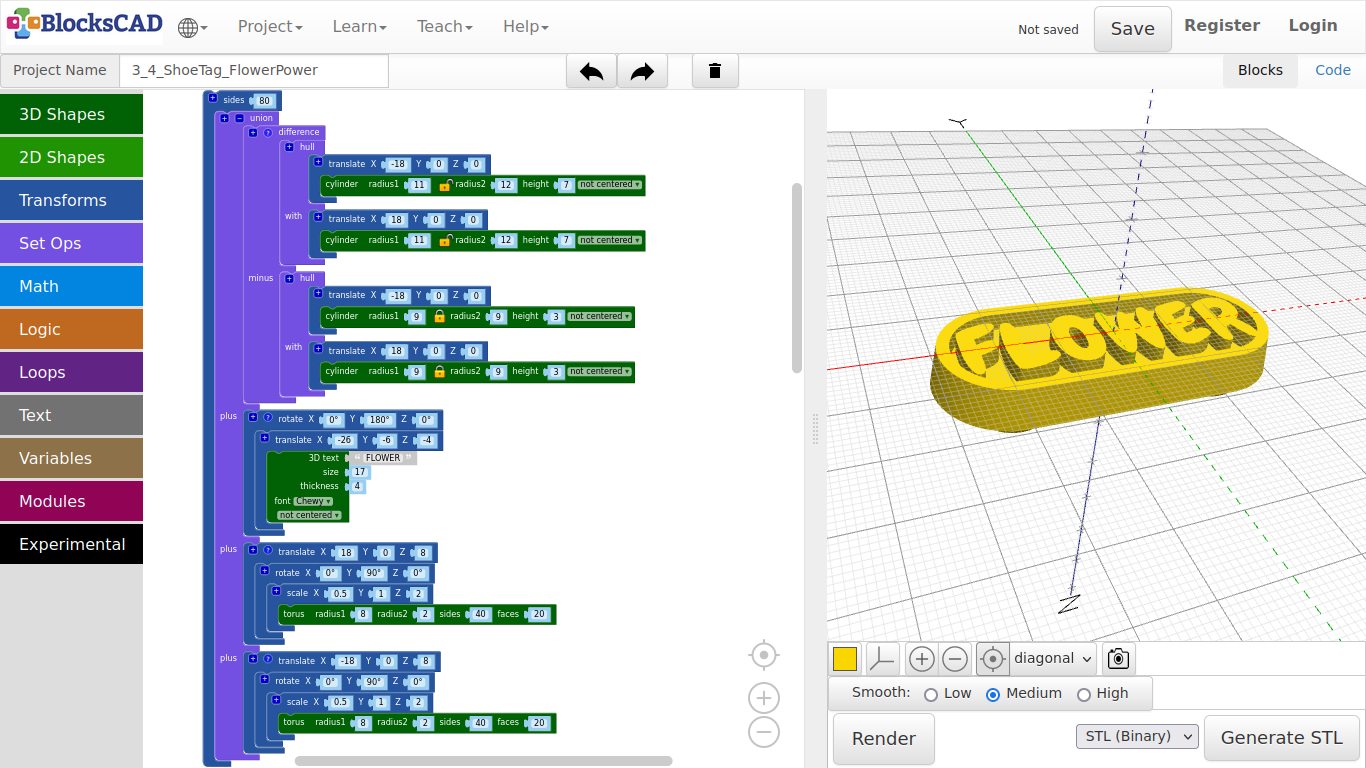
Now you should see an area that is cut out of the base. Lets add the word "Flower" to it.
-
Drag and drop one 3D text block from Text, one translate and one rotate from Transforms, and one union from Set Ops onto your workspace.
-
First lets get union ready for all block groups by using the + sign to add two more slots, so we have four slots.
-
Plug in the base block group into the first slot.
-
Next, plug in the 3D Text block into translate and change the values to 3D text: FLOWER, size: 17, thickness: 4, font: Chewy.
-
Drag this translate block with the text into rotate, and change the values of translate to X: -26, Y: -6, Z: -4.
-
Change the Y value of rotate to 180.
-
Plug the rotate block group into the second slot of union.
-
Press Render.
Now the word is in place! But there is nothing, we can attach it to our shoe laces yet.
Lets do that now!
-
Drag and drop one torus from 3D Shapes, one scale block + one translate block + one rotate block from Transforms onto your workspace.
-
Plug the torus block into scale, and change its values to radius1: 8, radius2: 2, sides: 40, faces: 20.
-
Drag scale with torus into rotate, and change the values of scale to X: 0.5, Y: 1, Z: 2.
-
As next take this rotate block and plug it into translate.
-
Change the Y value of rotate to 90.
-
Finally change the values of translate to X: 18, Y: 0, Z: 8.
-
Press Render.
We created one side of the lace hole. Before we continue with the second hole, change the positions of "translate", "rotate", and "scale" within the block group. Render it, after you changed it.
Can you see!?
Order matters in this case. The program will start with the lowest instance, which is the "torus", then it does the next action above, up and up as many of those are in on encapsulated group. Get back the original order, but keep this in mind when you model your own designs.
Back to the second hole for our show laces.
-
Select the translate block group we worked on, and duplicate it.
-
As all stays the same, but the position, change the Y value of one translate block to -18.
-
Plug both translate block groups into the third and fourth slot of union.
Before we do a final render, lets increase the smoothness through more squares used to create the model.
-
Drag and drop one sides from Transforms into your workspace.
-
Plug the entire block group union into sides, then change its value to 80.
-
Press Render.
Printed example:
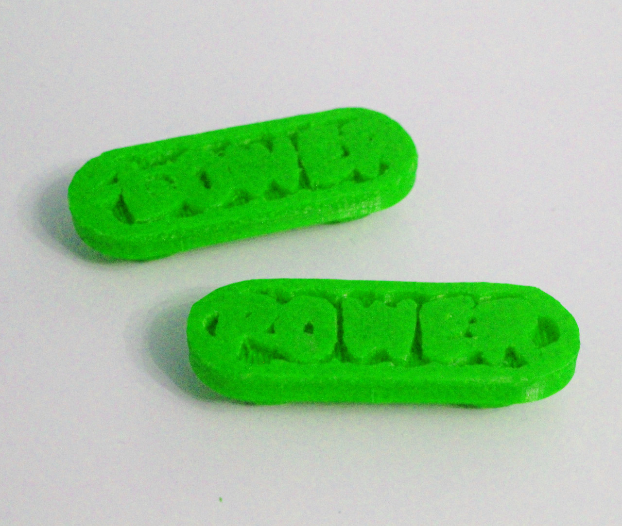
Exercise:
Add your own words to the shoe tag, or use other shapes to build a graphic!
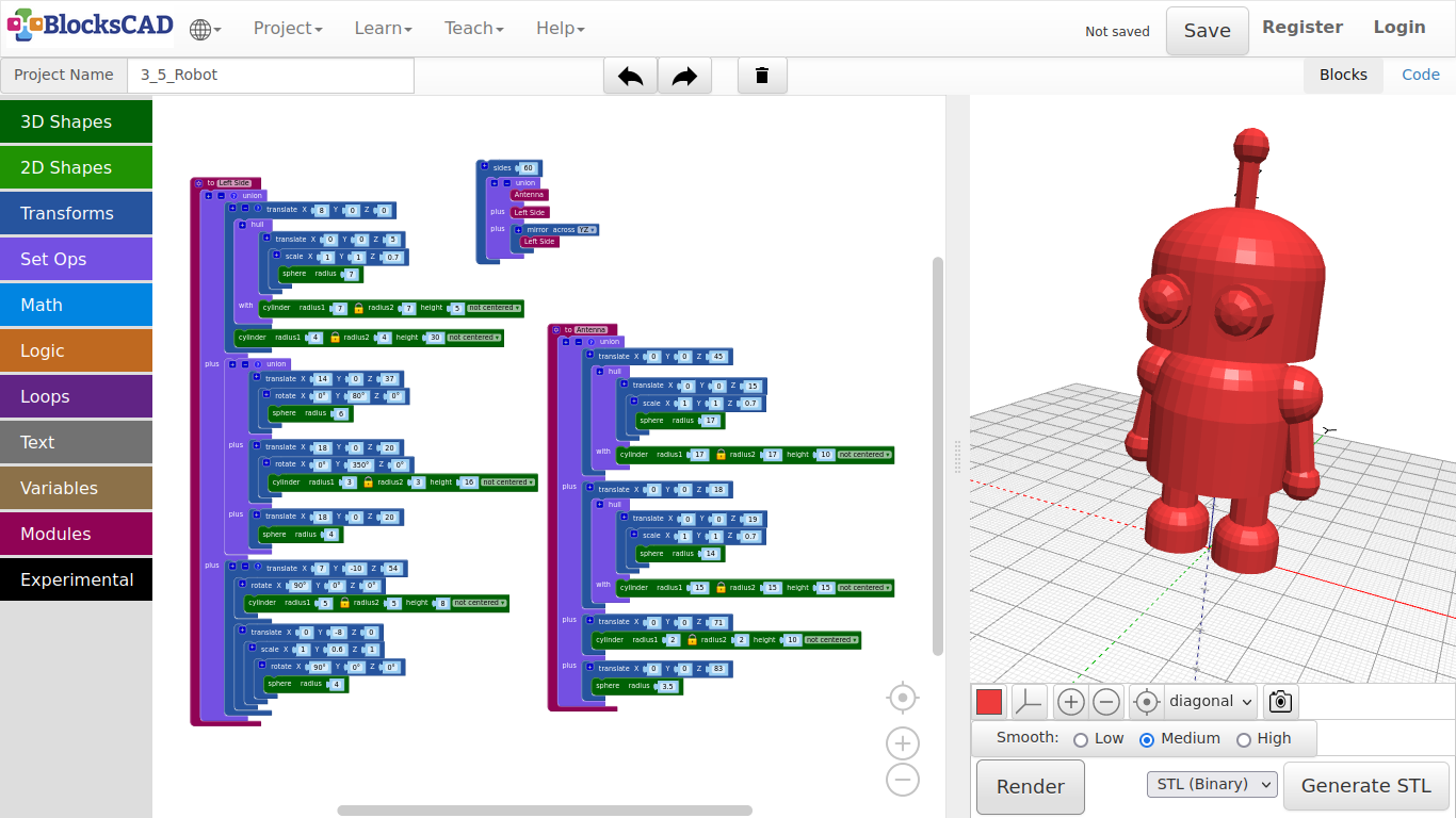
4.5. Robot 1
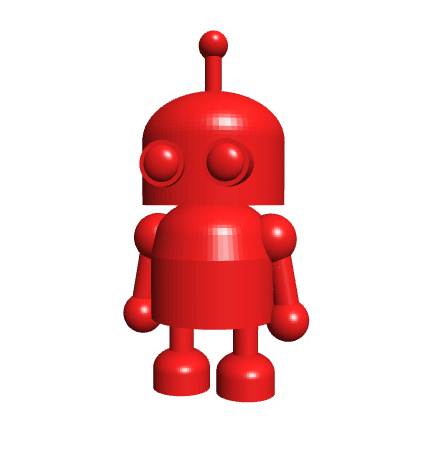
This robot has the most parts of all the other models we did together. I will show you, how to make things simpler, if you think first, after you made you sketch of a new thing you want to create.
So, lets get started!
- First open a new project and name it Robot.
We will do the body and head, including the antenna.
Lets start with Head of Robby!
- Drag and drop one cylinder and one sphere from 3D Shapes, one scale and two translate blocks from Transforms and one hull form Set Opts onto your workspace.
We will use hull() to create one shape from a sphere and a cylinder.
-
Add following values to the cylinder: radius1 = 17, height = 10.
-
The sphere block has a radius of 17 as well.
-
Plug the sphere into scale, and change the value of Z to 0.7.
-
Plug the scale block into one translate block.
-
Change the values of Z to 15.
-
Render it!
So, this are the 2 object we want to combine to one.
-
Plug translate with the sphere in it into the first position of hull.
-
Then place the cylinder block in the second position called with.
-
Render again! See!?
-
Now plug the hull block into the second translate, so we can put the head in place.
-
Change the Z value of translate to 45.
As next, we create the body by duplicating the entire block.
- Duplicate the entire block you just created.
Start to change the values of the copy from up to down.
-
Change the Z value of the top translate to 18.
-
Change the Z value of the translate block in first position of the hull block to 19.
-
Change the radius of the sphere to 14.
-
Change radius1 of the cylinder in the second slot of hull to 15, and the height to 15 as well.
-
Press Render!
Now you should see the body and head! Next we will create the antenna on top of the head, and group all together.
-
Drag and drop on union from Set Opts, one cylinder and one sphere from 3D Shapes, and two translate from Transforms onto your workspace.
-
Change the values of cylinder to radius1 = 2, height = 10.
-
Now plug it into one translate and change the Z axis to 71.
-
Continue with the sphere by changing the radius to 3.5.
-
Plug it in the second translate block, and change its Z value to 83.
-
Lets group all 4 blocks to one by creating 4 free slots in union using the + symbol two times.
-
Plug all parts in.
-
Press Render.
Now you should see an antenna on the head on its torso. Lets create a module from this entire *union* block.
-
Drag and drop one to do something from Modules onto your workspace.
-
Now, plug the entire union block into the to do something block.
-
Rename to do something into to head.
-
Now drag and drop the new block called head from Modules onto your workspace.
-
Render it!
Now we will create the leg, the arm and the eye on one side, starting with the leg. As it will look similar to the body and head, you can again create a duplicate of either by clicking on the to head module including the translate and hull blocks.
-
Change to head into to left side.
-
Change the values of translate to X = 8, Y = 0, Z = 0.
-
In the second translate, change the values to X = 0, Y = 0, Z = 5.
-
The radius of the sphere block becomes 7, as well as the cylinder radius1 with a height of 5.
-
Render it!
This is the foot, so we need to add the rest of the leg.
-
Drag and drop one cylinder from 3D Shapes onto your workspace.
-
Change the values of cylinder to radius1 = 3, and height = 30.
-
Now, use the + symbol of the foots first translate block to get another slot for the leg.
-
Plug in the cylinder block.
-
Press Render!
You should see now the leg with the foot connected to the body.
Lets continue with the arm!
- Drag and drop two sphere and one cylinder from 3D Shapes, two translate from Transforms, one rotate block from Transforms, and one union from Set Opts onto your work spaces.
Let start with the shoulder!
-
Change to radius of one sphere to 6, then plug it into rotate.
-
Change the Y Axis to 80 degrees.
You need to write it in, as the wheel does not have 80 degree to set.
-
Next, plug the rotate block into a translate block, and change to values there to X = 14, Y = 0, Z = 37.
-
For the rest of the arm, take the other translate and use + symbol to add a second slot.
-
Change the values of that translate module to X = 18, Y = 0, and Z = 20.
-
Take the second sphere and change its radius to 5, then plug it into one slot of that translate block with 2 slots.
-
Now change the values of cylinder to radius1 = 3, and height = 16.
-
Then plug it into the second rotate block. The Y Axis here needs to be 350 degrees.
-
Now plug in the rotate block with the cylinder into the second free translate slot.
-
Then group the shoulder and arm with hand together by plugging it all into the union block. Add one slot for union using +.
Now we create the eye on that side!
-
Drag and drop one sphere and one cylinder block from 3D Shapes, two translate + two rotate + one scale from Transforms onto the workspace.
-
Lets start with changing the cylinder values to radius1 = 5, height = 8.
-
Plug the cylinder block into one rotate block.
-
Change the X rotation to 90 degrees.
-
Then plug it into one translate block, and change that values to X = 7, Y = -10, Z = 54.
-
Add another slot to this translate block by using the + symbol.
We will build now the other block, that is going to plugged in there.
-
Change the radius of sphere to 4, then plug it into the second rotate block.
-
Change the X rotation to 90 degrees, and plug this into the scale block.
-
The scale value of Y needs to be change into 0.6.
-
Plug this module containing the sphere into the second translate block.
-
Change there the Y value to -8.
-
This block goes now into the free slot of the first translate block.
-
Now lets group the leg, the arm, and the eye using the leftover union block. You need to add one free slot.
-
Drag and drop the new block Left side from Modules onto the workspace.
-
Now press Render.
Now you should see the eye as well with all other parts on one side. We do not need to model everything again for the other side.
-
Just drag and drop one Mirror across XY from Transforms into the workspace.
-
Click on XY and change it into YZ.
-
Then make a duplicate of the Left Side block.
-
Plug it into the mirror block.
-
Render it!
The robot is finished!
But hold on, we want to have the robot a bit smoother. So we group all together and use sides again!
-
Drag and drop one union from Set Opts, and one side from Transforms into the space.
-
Use the + button to add one slot and add all 3 module blocks head, Left side and mirror with Left side into union.
-
Now plug the union block into sides, and change the value to 40.
-
Render it!
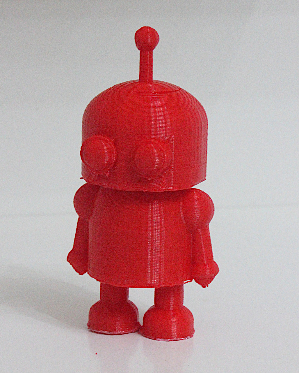
A voila!
Printed example:
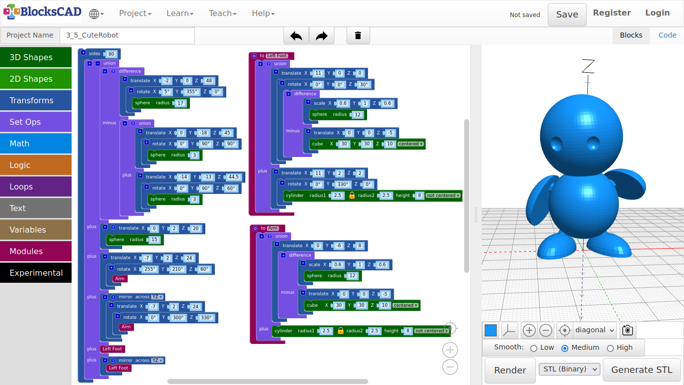
4.6. Robot 2
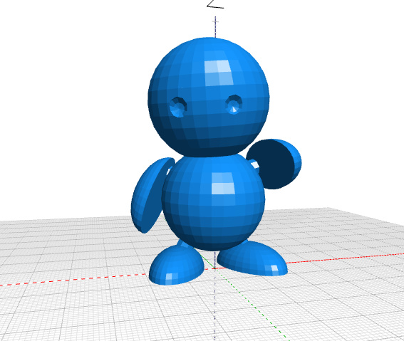
Here is a second robot, that looks a bit like the robot Marvin from "Hitchhiker's Guide To The Galaxy".
Lets start with the head!
-
Drag n drop one sphere from 3D Shapes, one translate and one rotate from Transforms onto your workspace.
-
Set the value of sphere to 17, and plug it into rotate.
-
Change the values of rotate to X: 5, Y: 355, Z: 0, and plug it into translate.
-
Change the values of translate to X: -2, Y: 0, Z: 48.
-
Press Render.
Now lets create the eyes.
-
Duplicate the entire block you just created for the head.
-
Change the values as follow: sphere to 3, rotate to X: 0, Y: 90, Z: 90, and translate to X: 0, Y: -18, Z: 45.
-
Duplicate this entire block again, keep the sphere value, while changing the values of rotate to X: 0, Y: 90, Z: 60, and translate to X: -14, Y: -13, Z: 44.5.
-
Now drag and drop one union block and one difference block from Set Ups into your workspace.
-
Plug both eye sphere blocks into the union block.
-
Then plug in this union block into the second slot of difference called minus.
-
Plug the head translate block into the first slot of difference.
-
Press Render.
This is the head that has now two eyes carved into it!* Let us continue with the torso sphere!***
-
Drag and drop one sphere from 3D Shapes, and one translate from Transforms onto your workspace.
-
Set the value of sphere to 15, and plug it into the translate block.
-
Change the values of translate to X: 0, Y: 2, Z:20.
-
Press Render.
Now lets create the foot of our little robot, starting with the leg!
Again, we will later use *mirror* for the second leg.
-
Drag and drop one cylinder from 3D Shapes, one rotate and one translate block from Transforms onto your workspace.
-
Change the value of cylinder to radius1: 2.5, height:8, and plug it into rotate.
-
Change those values to X: 0, Y: 330, Z: 0.
-
Then plug rotate into translate and change the values of translate to X: 11, Y: 2, Z: 2.
-
Press Render.
The leg is done. Now we will create a foot by using a sphere and cutting it into half.
-
Drag and drop one sphere as well as one cube from 3D Shapes, two translate blocks + one rotate block + one scale block from Transforms, and one difference block from Set Ops onto your workplace.
-
Change the value of sphere to 12, and plug it into scale.
-
Change the values of scale to X: 0.6, Y: 1, Z: 0.6, and plug it into the first slot of difference.
-
Take the cube block, change the values to X: 30, Y: 30, Z: 10, centered, and plug it into the second slot of difference.
-
Plug in the entire difference block into rotate.
-
Change the Z value of rotate to 30.
-
Then plug rotate with difference into translate, and change the X value of translate to 11.
-
Press Render.
Now you should see one leg and foot on one side.
Lets build a module of the leg and mirror it!
-
Drag and drop one union block from Set Ops, and one to do something block from Modules onto the workspace.
-
Rename the to do something block to to Leg, and drag in the new generated Leg block from Modules onto your workspace.
-
Now plug the block collection translate of the foot, and translate of the leg into union, then union into to Leg.
-
Press Render.
Now the leg is ready to get mirrored. If you can not see the leg, then your forgot to drag in the "Leg" block from "Modules"!
-
Now duplicate Leg one time, and drag and drop mirror across from Transforms onto the your workplace.
-
Change the value of mirror across to YZ, and plug one Leg into it.
-
Press Render.
You should see now 2 legs with feet on the right positions. Ready to create another module for the arm?
Lets go!
-
Drag and drop one cylinder, one cube, and one sphere from 3D Shapes onto your workplace.
-
Furthermore, drag and drop one scale, two translate, and two rotate blocks from Transforms into your space.
-
Finally drag and drop one union and one difference block from Set Ops + one to do something block from Modules onto your workspace.
-
Rename to do something to to Arm, and plug in union.
-
Change the values of cylinder to radius1: 2.5, height: 8, and plug it into the second slot of union.
Now lets create something similar to the foot. This time we will use it as arm.
-
Change the value of sphere to 12, and plug it into scale.
-
Set the values of scale to X: 0.6, Y: 1, Z: 0.6, and plug it into the first slot of difference.
-
Now change the values of cube to X: 30, Y: 30, Z: 10, centered, and plug it into translate.
-
Change the value Z of translate to -5, and plug this one in the second slot of difference called minus.
We need to move the arm up a bit, as the center of the arm will be the bottom of the cylinder.
-
Plug difference into the last translate, and change those values to X: 0, Y: -6, Z: 8.
-
Now plug in translate block into the first slot of union.
-
Drag and drop the Arm block that got generated from Modules onto your workspace.
-
Press Render.
Well, that looks odd! Does it not? Lets move the arm to a nice position!
-
Drag and drop one translate block and one rotate block from Transforms onto your workplace.
-
Take the Arm block, and plug it into rotate.
-
Change the values of rotate to X: 255, Y: 210, Z: 24, and plug it into translate.
-
Now change those values to X: -7, Y: 2, Z: 24.
-
Press Render.
See!? Now lets use the module "Arm" for the other side, but lets change the position a bit to make it look a bit more interesting.
-
Duplicate the translate block including rotate and Arm.
-
Drag and drop mirror across from Transforms into the workspace, and change the value to YZ.
-
Plug in the arms duplicate, and change the rotate values to X: 0, Y: 300, Z: 330.
-
Press Render.
Well, there is Marvin. But hey, lets smooth the surface for it. The print will look much better!
-
Drag and drop one union block from Set Ops, and one sides block from Transforms onto your workspace.
-
Use the + symbol to add four more slots to union.
-
Plug in the head, torso, both arms and both legs into the union block.
-
Then plug in the entire union block into sides, and change its value to 80.
-
Press Render.
Be patient, this are lot of faces BlocksCAD needs to render.
If you want to work on the pose of your robot, change the "sides" value down to 12 or so!* This will shorten the render time tremendously!***
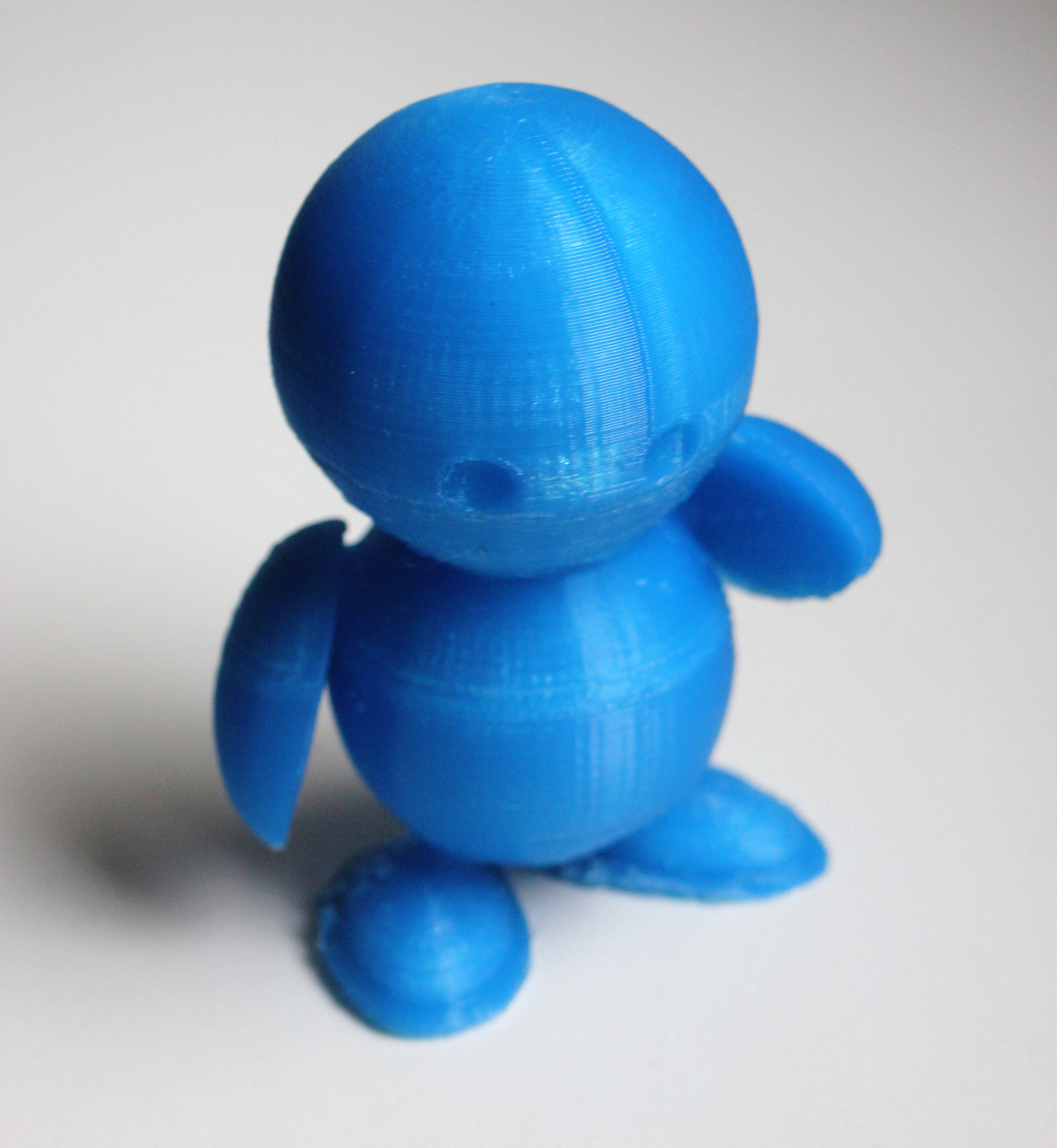
Printed example:
5.1. Slice with Kiri (Online)
Checklist for the printer:
- Do you have enough filament on your spool?
- Did you replace the blue tape, that can not be reused?
- Is the print head releasing plastic when preheating?
- Is your print plate clean?
Following section will introduce you to 2 option to prepare your object to be printed.
- Use kiri:moto website to slice objects
- Use Prusa Slicer software to slice objects
Use kiri:moto website to slice objects
This section shows you, how to use the online STL to GCODE slicing using a web browser application.
- Use following settings, if you have purchased an EasyThreedX1 or EasyThreedX2 printer:
- The web browser will save your settings on your device, and use it automatically next time you open this url.
- Therefore, the next steps only need to be done once.
- However, there are settings in infill and support, that might change depend on your object you want to print.
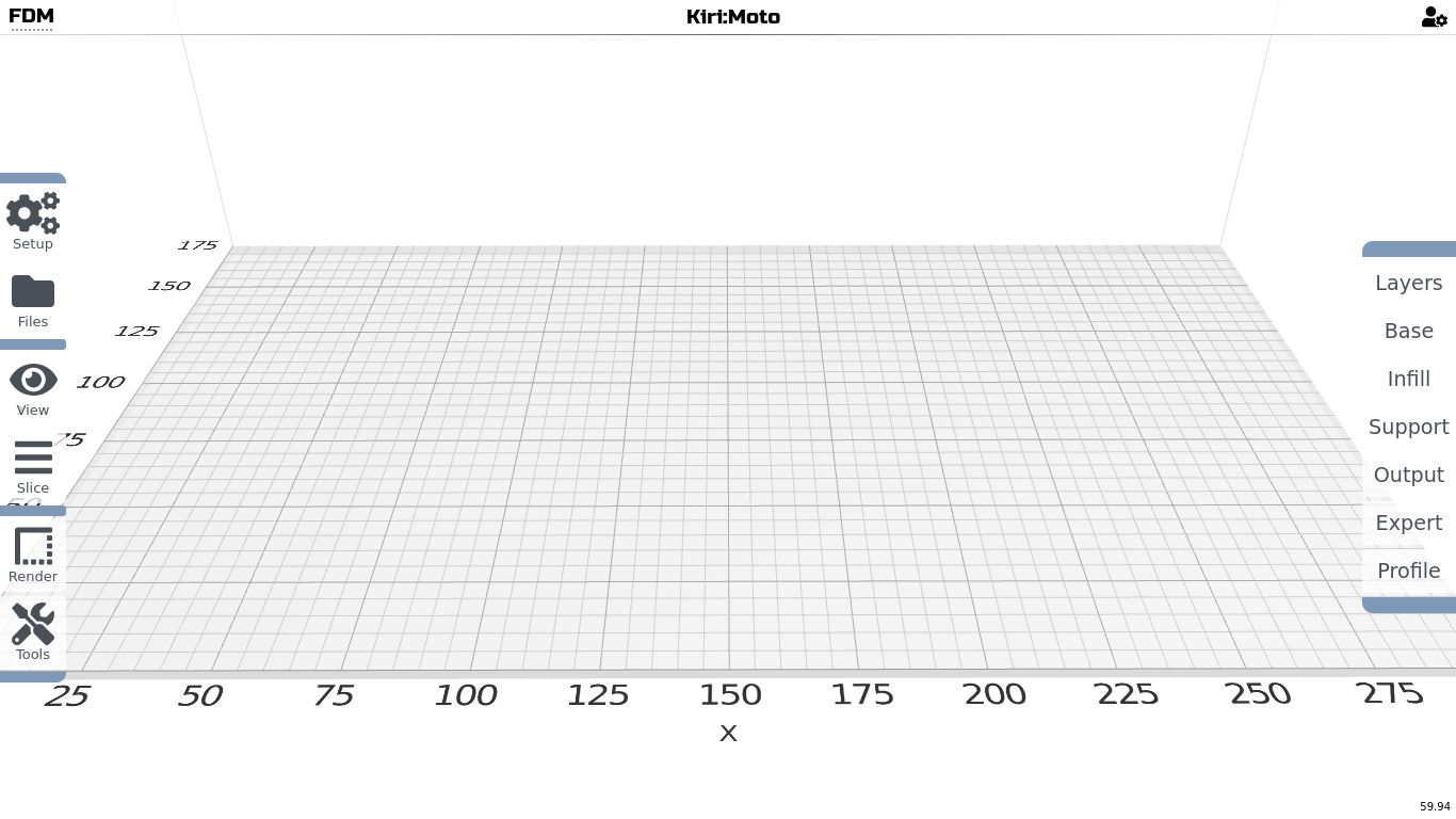
- Lets start with the setup by choosing >> Setup >> Machine.
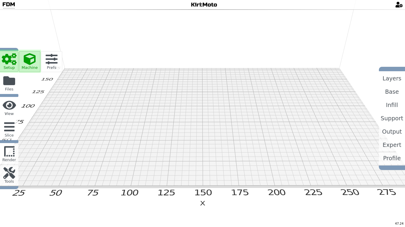
- Choose the standard devices Creality Ender 6, as it is the closed to EasyThreeD printers.
- Then press Customize.
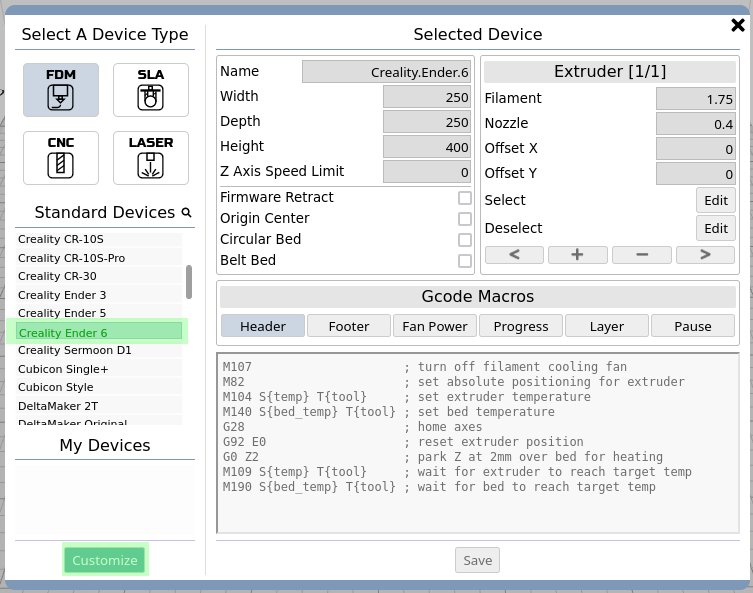
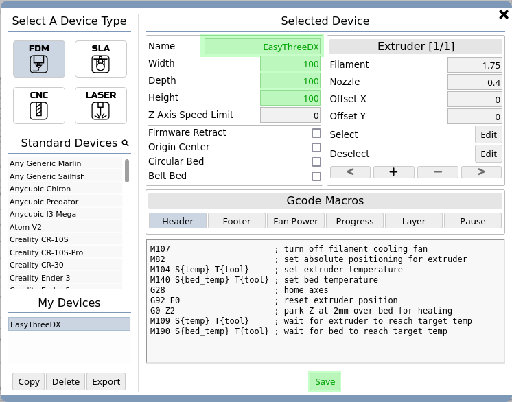
- Now you can change the name to create your own Device. You will see any customized printer in the list My Devices.
- Next, change the Width, Depth, and Height to 100.
- Press Save.
- As you can see, the printing space is has changed.
- Now go to the right side panel and choose the section step-by-step.
- Change the values as shown in the pictures below.
- This will setup the printing settings.
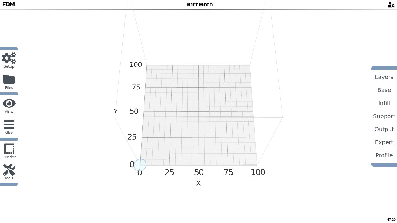
- Layers: Here you can choose how fine the print is going to be printed.
- The higher the layer the more rough the print, and the shorter is the printing time.
- The lower the layer height the finer the print, but the longer is the printing time is going to be.
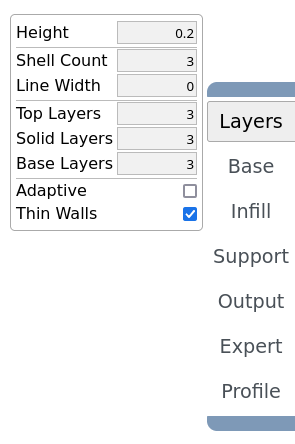
- Base: is all about the bottom of the print and printing speed.
- Many of the values are 0, which will then be the default values set in other settings sections. e.g. Nozzle temperature in Output
- E.g. change the temperature, if you would like to print lower or higher than 210 degree Celsius.
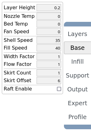
- Infill: dedicates the filling of your object, what pattern and how dense it is going to be printed.
- With Fill Type you decide what pattern is the filling going to be.
- With Fill Fraction you will decide the density (0: No filling, 1: Full fill)
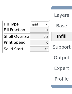
- Support: Sets the values of the supporting structure.
- Here you can experiment mainly with Density, and Pillar Size.
- Press Detect to see the estimation of the supporting material as soon you loaded your object.
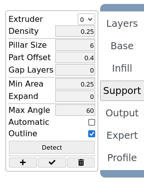
- Output: are the values of nozzle temperature, fan speed, and printing speed.
- You will not change these values much.
- Do not go over a printing time of 40 mm/s in Print Speed, as this is the maximum printing speed of the EasyThreeD X1/2 printer.
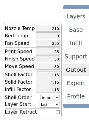
Expert:
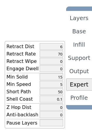
- Profile: saves your printing settings, so you can call it in the future.
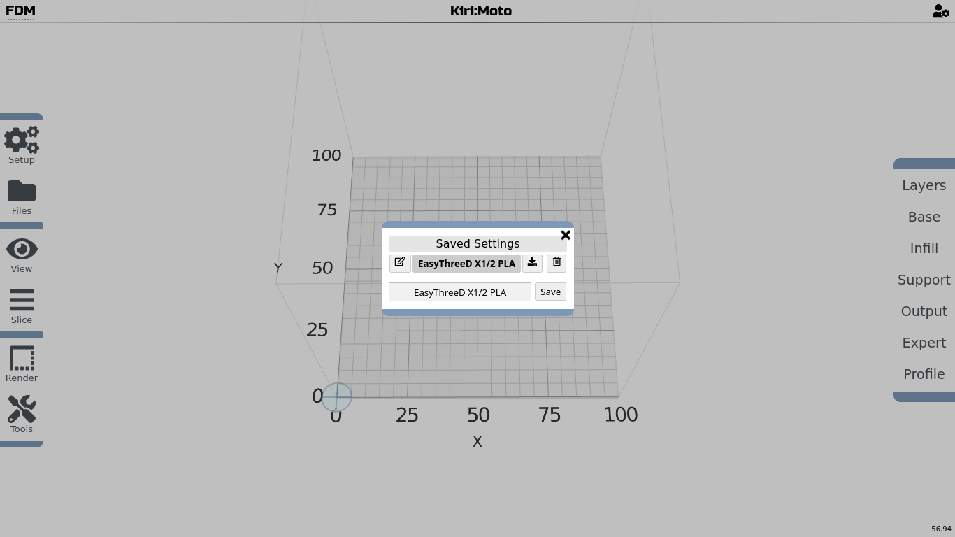
Now that the printer settings are applied, lets import an object and slice it:
- Go to >> Files >> Import, and choose your object file in .stl format.
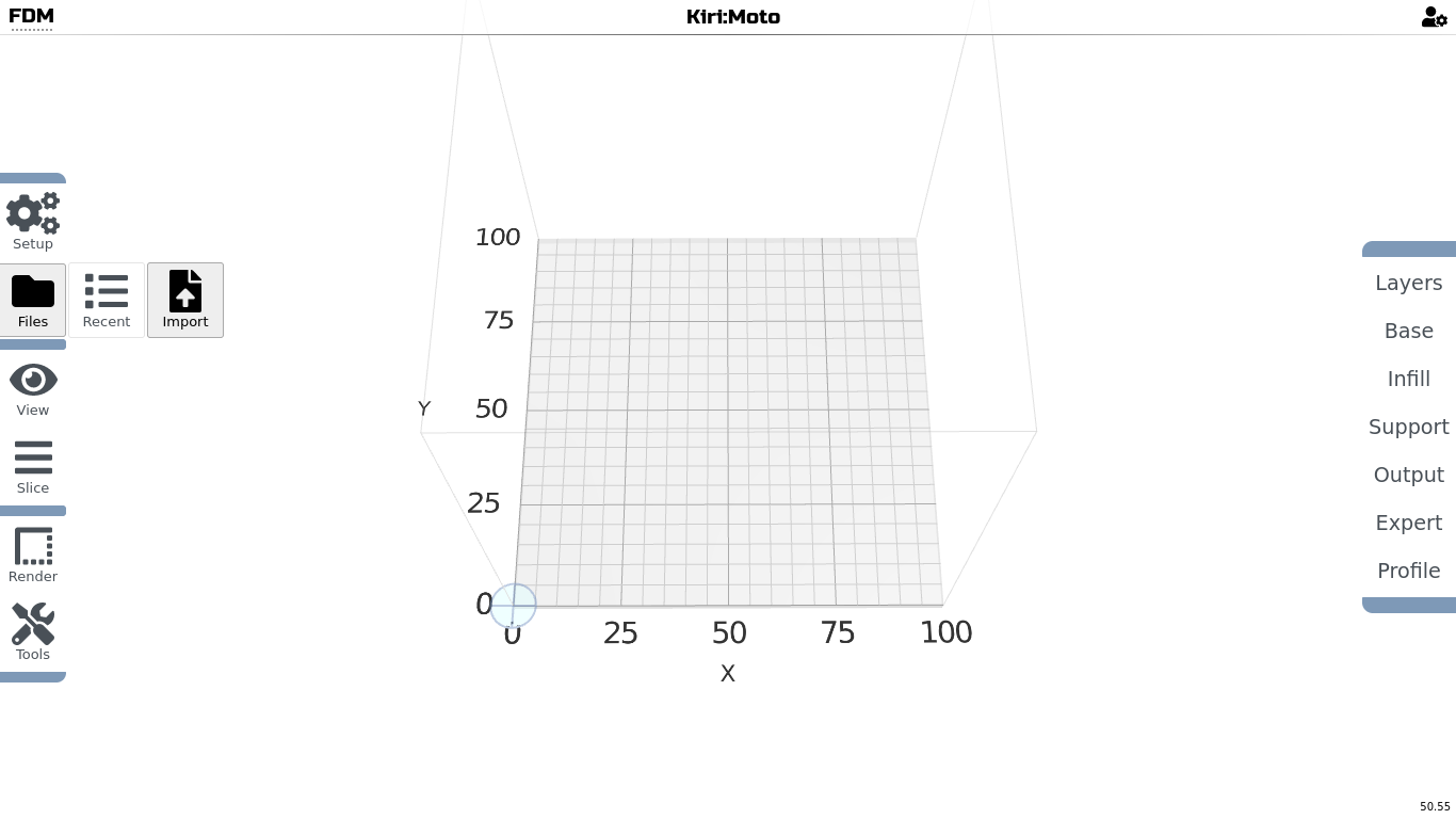
- It should show up in the center of your printing space. You can import more objects, that will then rearrange on the printing platform.
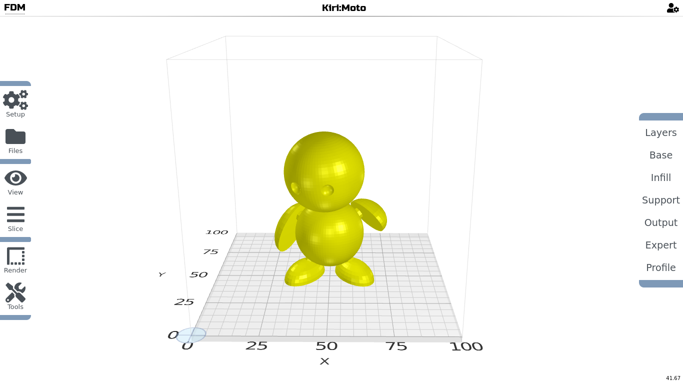
- In the example of Marvin, you will need support printed. Choose >> Support >> Detect to see the estimation. Test different values, if you have too little or too much support material.
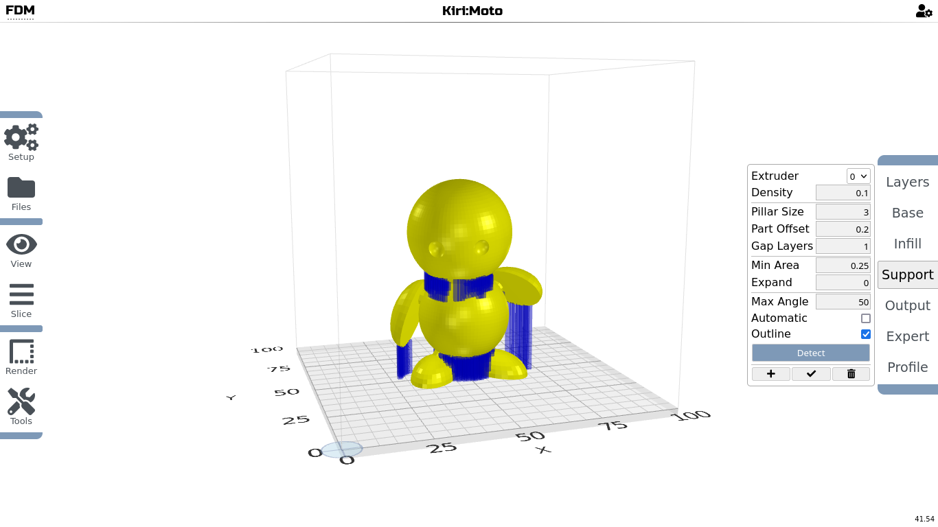
- Now go to >> Slice >> Preview, and click to start to render a preview.
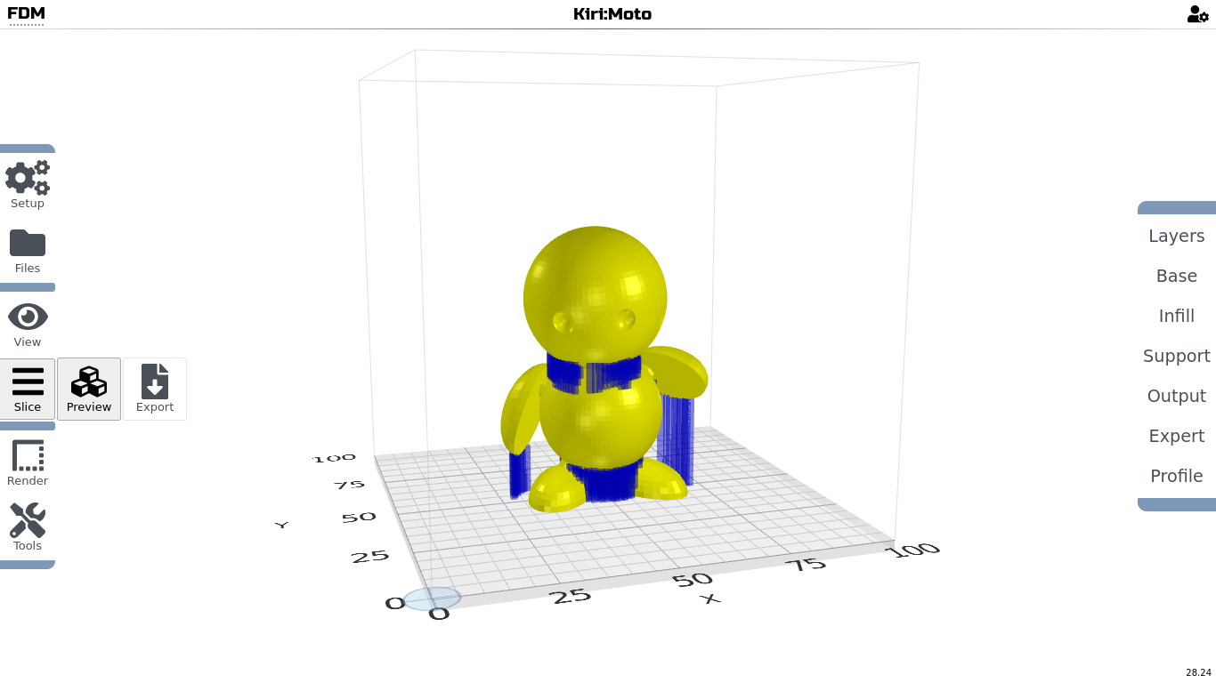
The preview rendering will calculate every print layer according to the printing settings in your profile.

- Use the slide on the bottom to check on infill density and support material.
Check, if it is printable (nothing starts in thin air, but is build from below up)
This option can be slow, as this will stress your devices graphics. Be patient. Move the slider a bit, then wait till the view is updated!
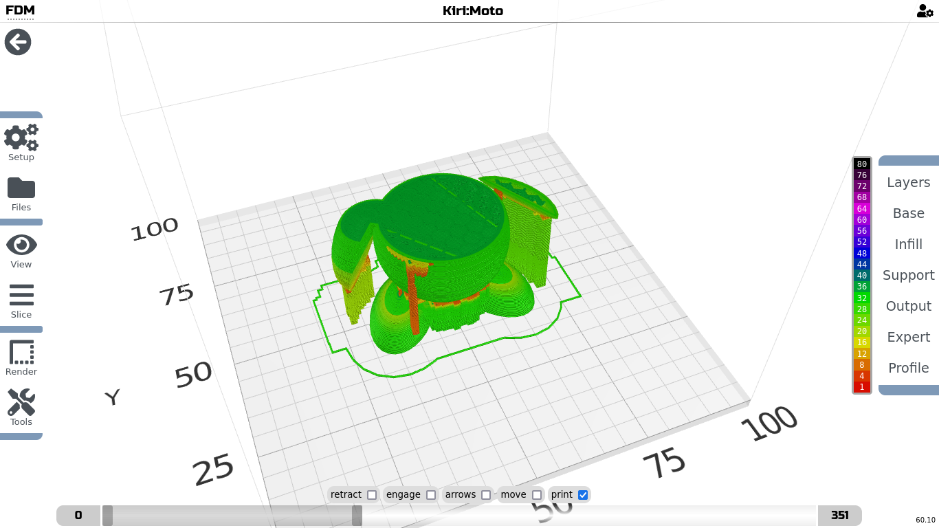
If you are satisfied with the rendered preview, you can export it as .gcode file.
- Press >> Slice >> Export.
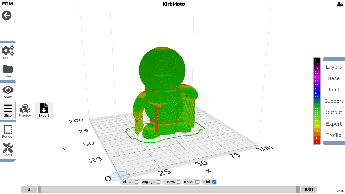
Now it will again calculate each layer, then open a Pop-up window with details, and an export button.
- Press Download, and save the file.
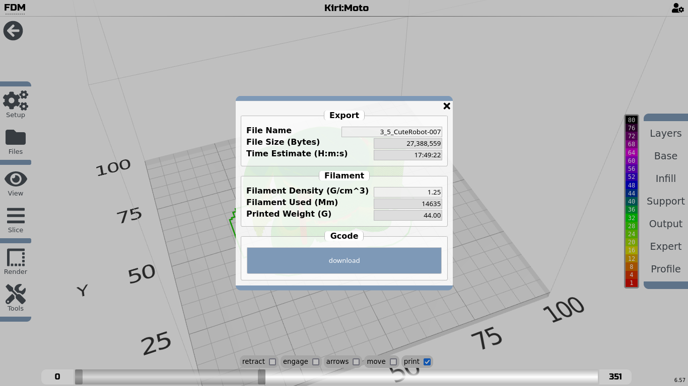
5.2. Slice with Prusa Slicer (Linux, Win, Mac)
If you have a PC or Laptop, you can use Prusa Slicer to prepare your exported 3D object for 3D printing.
Download Prusa Slicer
The Moodle offline server Linux Distribution has it installed and configured already.
Go to Menu >> Education >> Prusa Slicer
Import the configuration file for your EasyThreedX2 printer (only once)
- Open Prusa Slicer
- Import the configuration file EasyThreedX2.ini by choosing File >> Import >> Import Config...
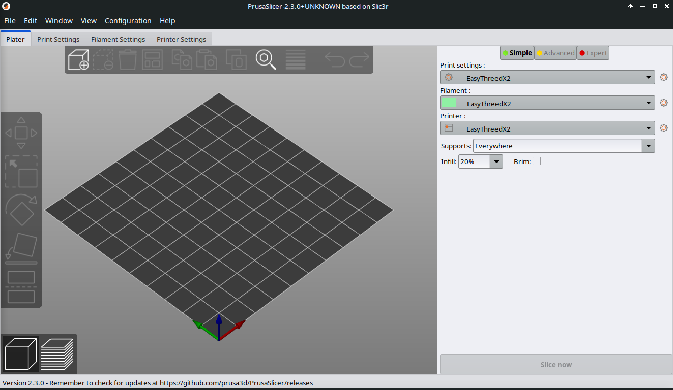
- Now you should see the configuration in the right side panel of Prusa Slicer.
Lets go through the most important settings. I will point you at settings, that you can change. This will be mostly in "Print settings".
If you use a different printer, you might need to change the settings and build your own configuration profile!
-
Click on Print settings:
-
This is the How to print section
- Most important are the first 4 subsections Layers and perimeters, Infill, Skirt and brim, and Support material.
- Layers and perimeters:
- Layer height >> Indicates thickness of each layer printed (0.2)
- First layer height >> Thickness of the first layer, that is often thicker than all other layers (0.25).
- The lower the layer height the finer your print result, but the higher the printing time.
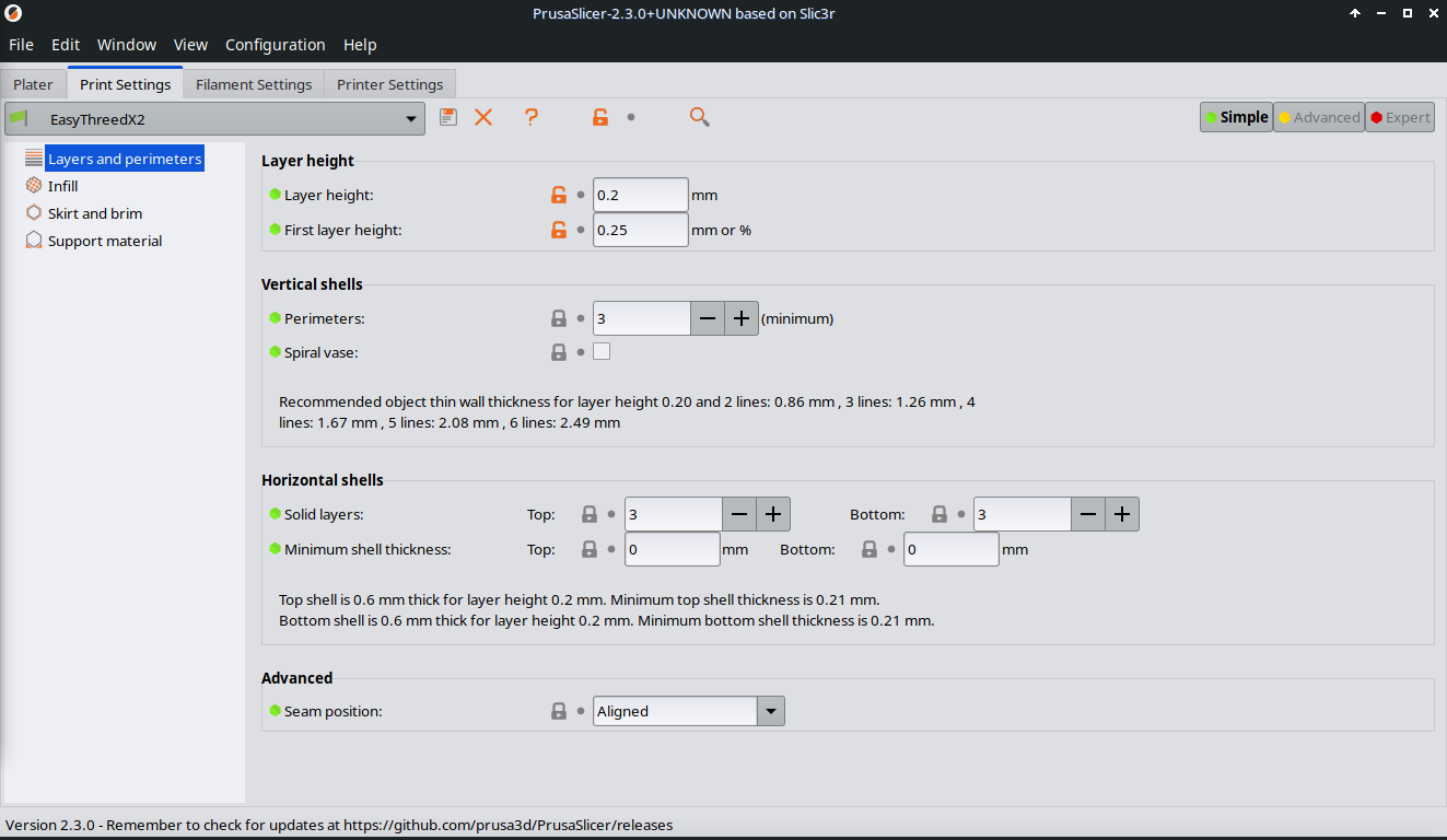
- Infill:
- Fill density >> Sets the density of the material within the printed object (20 %)
- 0 % density will keep the object hollow, thus only print the walls.
- 100 % density will print the object as a full solid.

- Skirt and Brim:
- Distance from object >> is the distance between skirt and objects
- Brim is a method to prevent wrapping of printed material when cooling down.
- Brim width >> how many mm width should go around the objects bottom layer
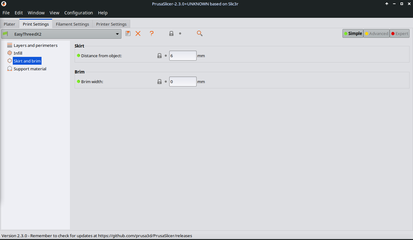
- Support material:
- Generate support material >> on / off activation
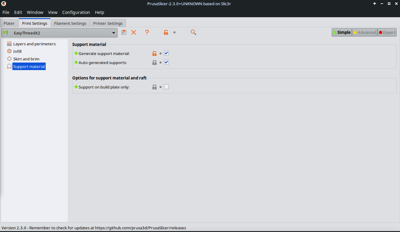
- Speed (not visible with Simple):
- Do not go over 40 mm/s in printing speed. This is the maximum the EasyThreedX2 can do!
- Travel speed is ok to be the double.
5. Click on Filament Settings
- Filament:
- Filament thickness will stay 1.75 mm with EasyThreedX2.
- If there are problems with printing you can try to change temperature, as the optimum is depend on the filament quality of PLA.
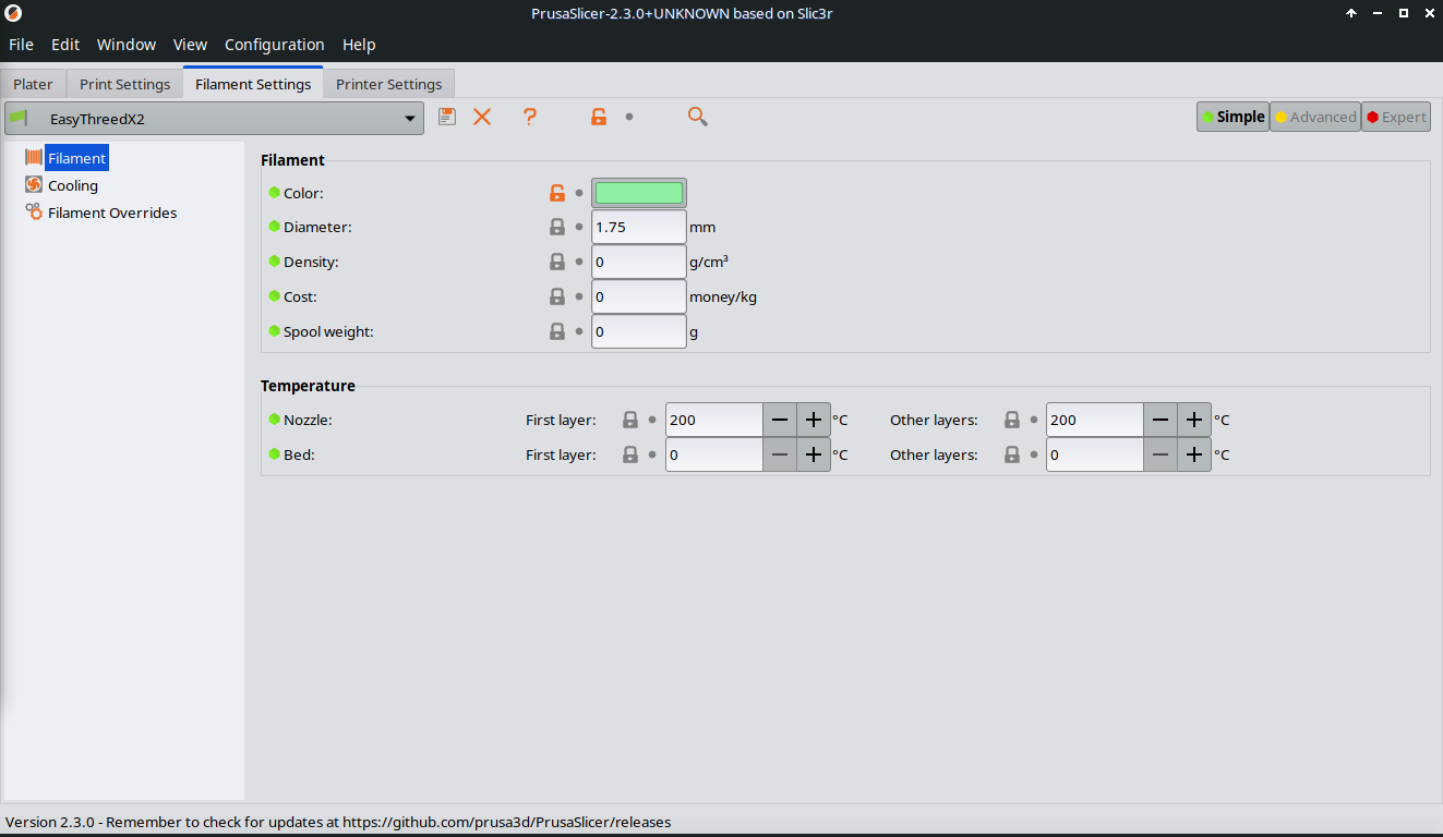
- Cooling:
- Also here, best is to leave it.
-
But sometimes it is better to switch off the cooling fan, or to keep it going all the time.
-
Click on Printer Settings
-
General
- Bed shape stays the same with 10 x 10 cm.
- Extruder 1
- Settings stay the same for EasyThreedX2
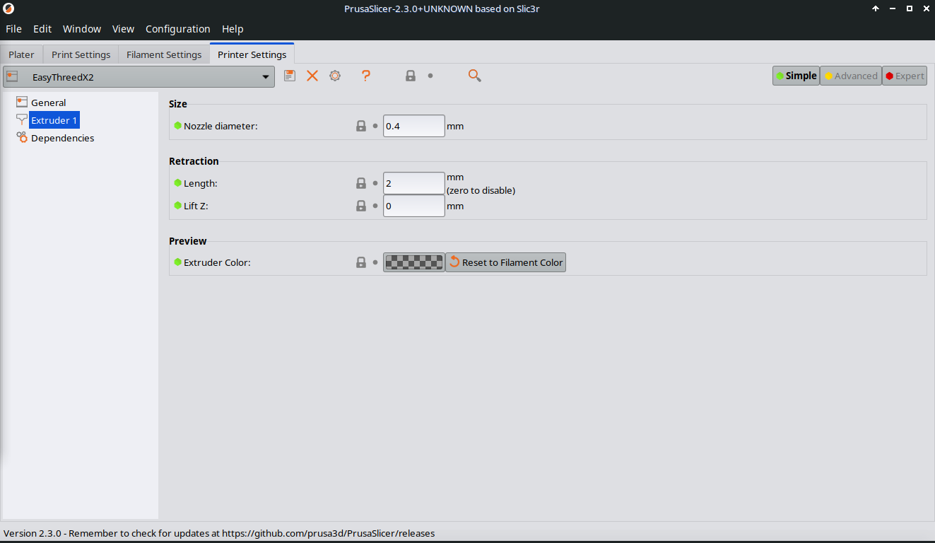
- Each time you change a value in all 3 main sections, the name will be automatically to name(modified).
- Click the floppy disk symbol to save the changed version.
This comes handy, if you want to use a version with different fillings, with or without support materials s.o.
- Rename it before you save, so you know, what has changed.
The configuration is saved, and will be called each time you start Prusa Slicer.
Slice your model in Prusa Slicer
- Open Prusa Slicer
- Press the Add button and choose your .stl file and open it.

Make sure you have all 3 parts of the EasyThreedX2 configuration set.
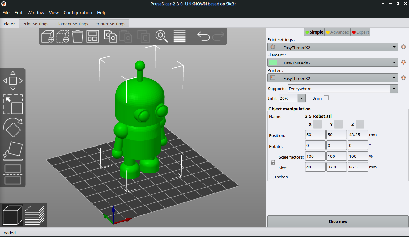
- Press Preview button to see settings executed on your object, or press Slice now button.

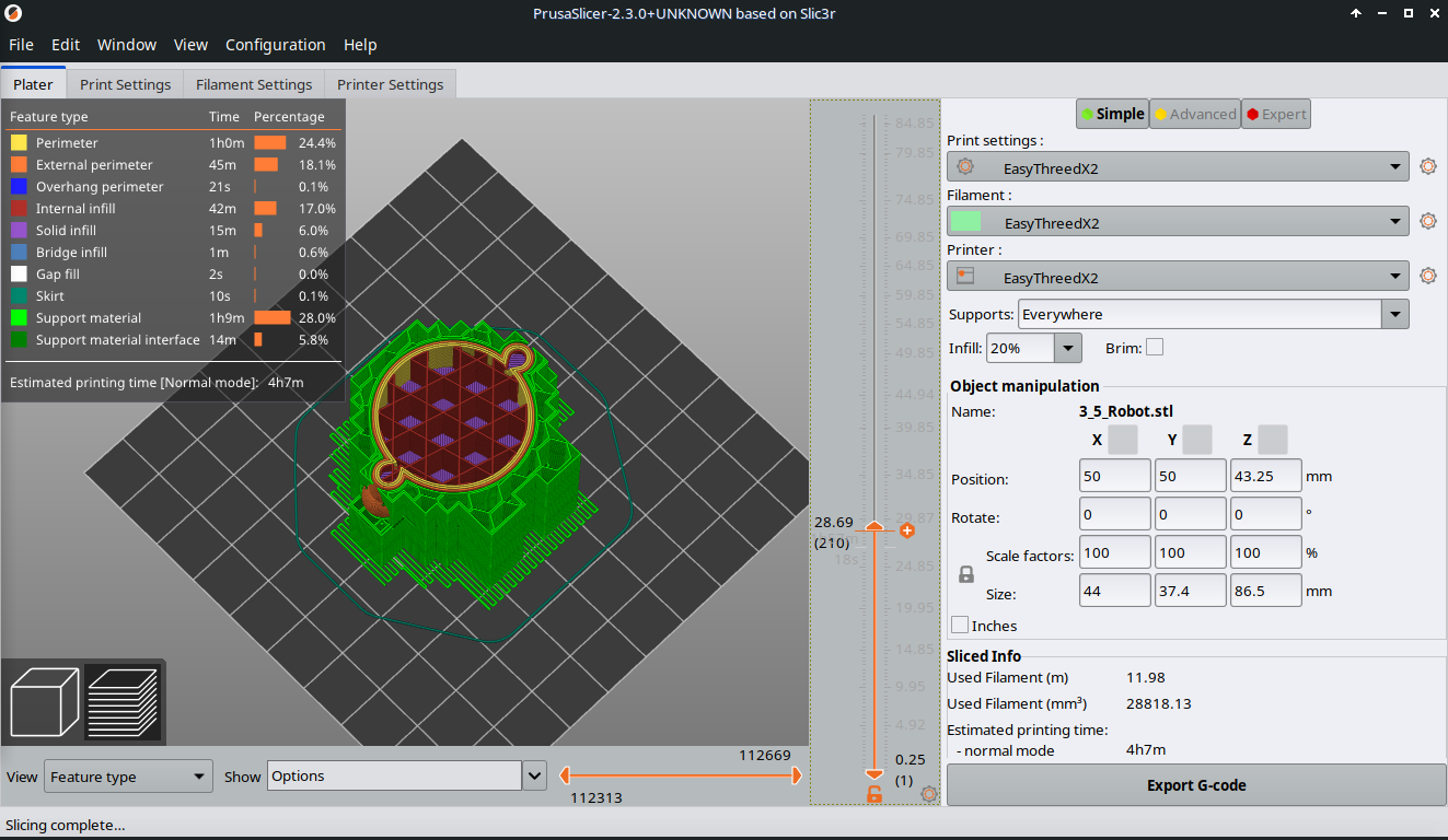
- Use the vertical slider to move through each layer. Check if there are impossible print situations (like the printer starts printing in middle of nowhere)
-
If everything looks good (also check, if you need support or not), the press Export G-code button.
-
Save it.
That's it! Next we will go through the possible ways to control the printer making it print the object using the gcode file.

6.1. My 3D Printer
The chosen printer is as a beginners printer perfect for kids. It is the EasyThreedX2, which is available already around 100 Euro.
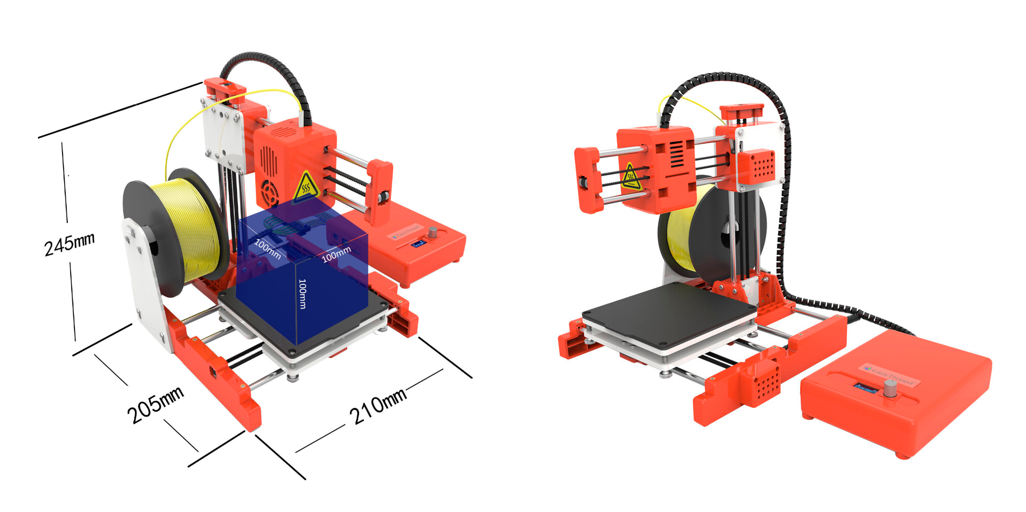
- The printer is easy to use and has pretty good reviews.
- It is a little printer, that has a 10 x 10 x 10 cm printing space and uses only 30 Watt of energy consumption. It has amazing printing results for its low price.
- If something is not working, it is easy to fix (out of my own experience).
- It is for PLA Plastic, a starch based Bio-plastic.
- With its light-weight and small size, it fits in bags to take it to school or friends.
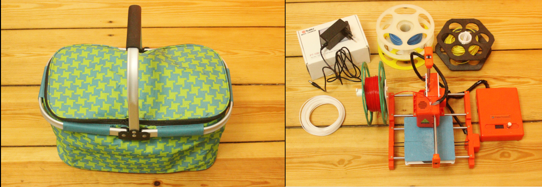
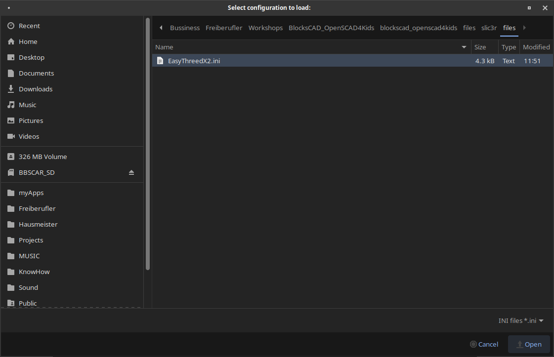
6.2. Prepare for printing
Checklist for the printer:
- Do you have enough filament on your spool?
- Did you replace the blue tape, that can not be reused?
- Is the print head releasing plastic when preheating?
- Is your print plate clean?
First things first
No matter which way you will control the printer, it is good to know how to do the basic procedures with the EasyThreeD X1/2 printer.
This procedures are often use with other printers as well...except the printer does it automatically (e.g. auto leveling).
The following occasional steps do not need to be done with each print. However, check on it!
- Use blue tape (or other paper tape) to protect your magnetic print bed surface.
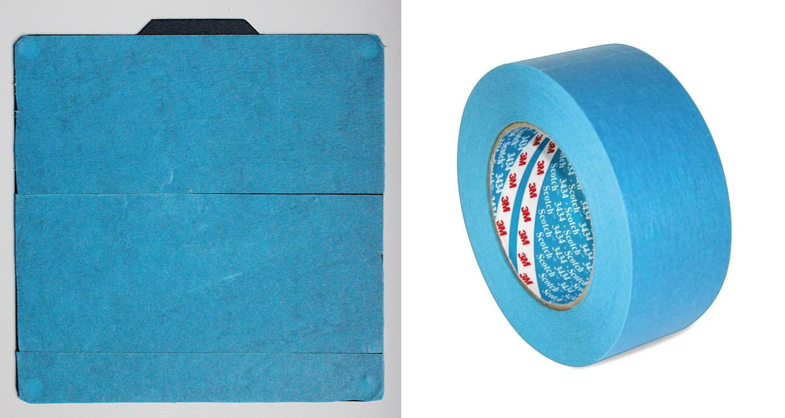
-
Level your bed to prevent the nozzle scratching into the print bed, or distance too far from the print bed.
-
Take a piece of printing paper, and put it onto your printers printing bed. You might cut the A4 paper in half.
- Go in the menu to >> Prepare >> Auto home. The printer head is going into the starting position.
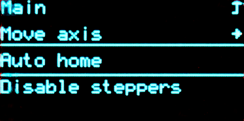
- Then move one down in the menu and press >> Disable Steppers to be able to move the print bed and printer head around with your hands.
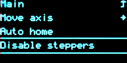
Start with the screw underneath the starting position, so you do not need to move anything for now.
Try to move the piece of printing paper. You should feel a soft resistance when moving the paper. You can use both hands holding both ends of the paper to make it easier to move.
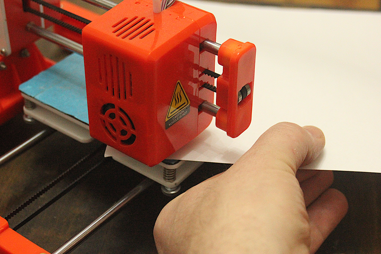
- Turn the screw in one or the other direction, if you can not move the paper or it is super easy to move.
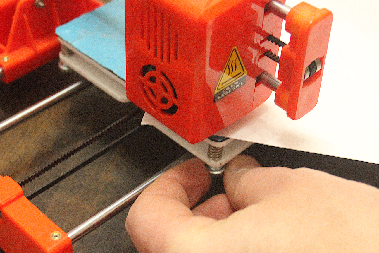
- Go through the next 3 corners and do the same thing.
Be careful, be gentle when moving the print bed and printers head, even if it is not so easy to move. After you did the leveling once, you barely need to repeat the procedure. It will be necessary once in a while depend on room temperature, or after you renewed the blue tape.
Blue tape set? Printer filament ready? Lets go!
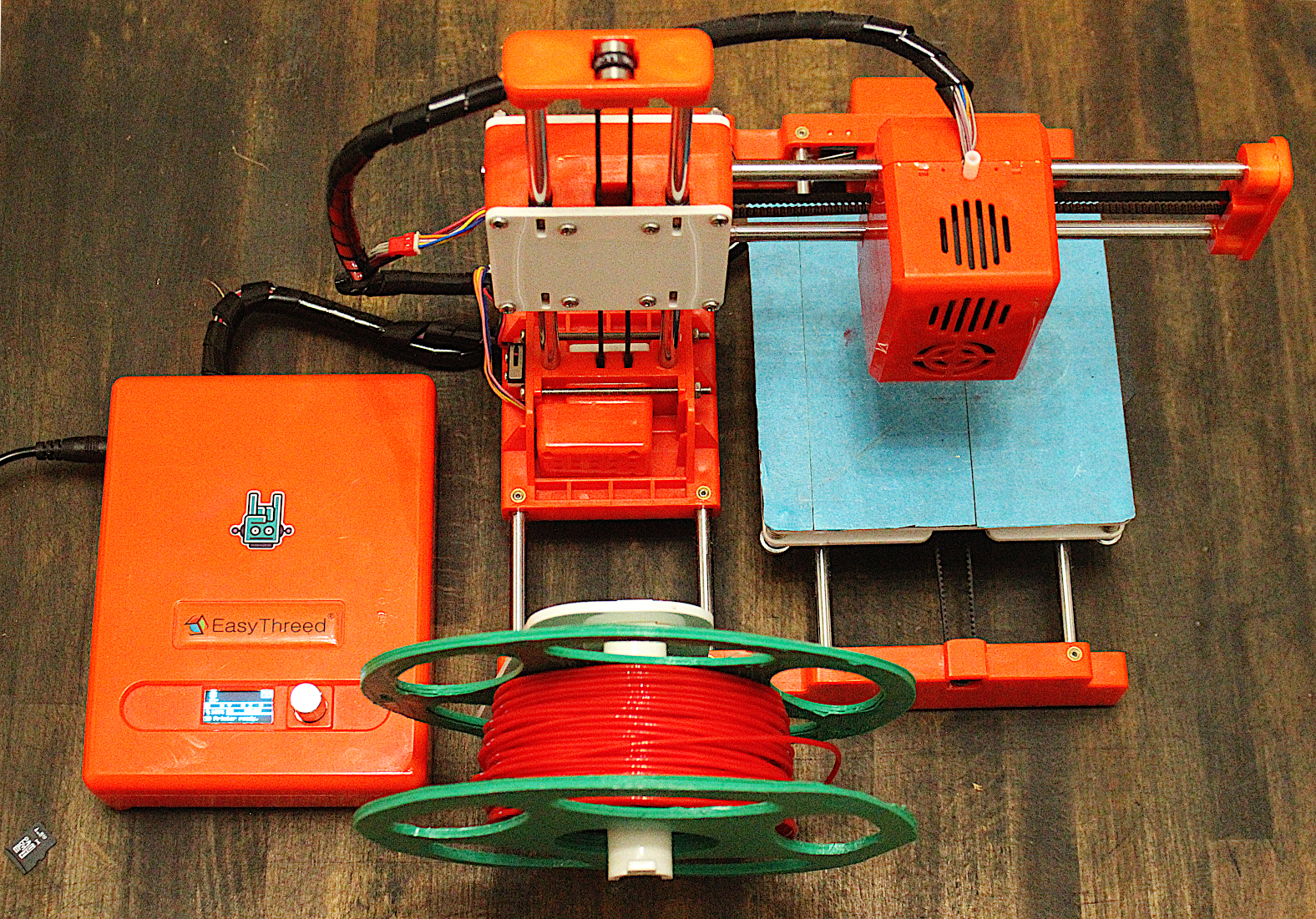
Ok, lets feed your printer with filament!
First, we want to move the printing head up so we can see the incoming filament and protect the printing bed from overheating.
The first screen you will see, after you start the printer is called Info Screen.
- Click once to open the main menu, using the knob that has an embedded button. You can turn the knob and press it.
- Click through following path: >> Prepare >> Move Axis >> Move Z >> Move 10 mm >>.

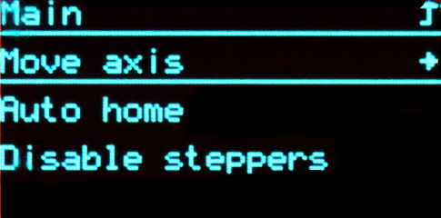
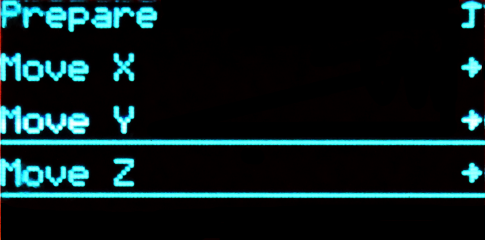
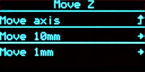
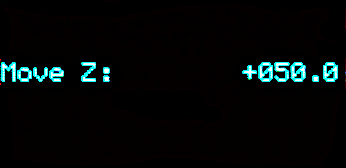
- Now turn the wheel clock-wise 2 - 3 steps.
The head will move up 20 - 30 mm. This should be enough.
- Go up to the first option in the sub menu and click to move back up in to the main menu.
If you wait for a while, the menu will reset automatically. Next, we want to add, or replace the filament.
- Go to >> Prepare >> In/Out Filament >>.
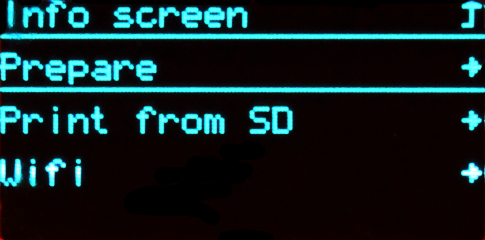
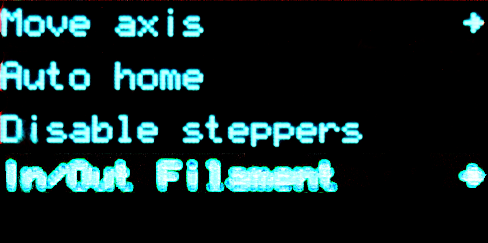
As soon your press In/Out Filament the printer will start heating up its printer head to 200 degree Celsius. Do not touch the nozzle!
- Now choose the option you want to do:
In Filament >> The extruder of the printer head will move the filament towards the nozzle, as soon 200 Degree Celsius is reached.
Out Filament >> The extruder of the printer head will move the filament away from the nozzle, as soon 200 Degree Celsius is reached.
Stop In/Out Filament >> Stops the extruder motor and the heater, thus cooling down the nozzle.
As soon you press In Filament or Out Filament you will see the temperature on top of the display.
- When the nozzle temperature reaches 200 degree Celsius, and you hear the extruder motor moving:
Push a bit the filament till you feel it gets drawn in.
On the other hand pull it a bit when removing the filament till it releases it from the extruder.
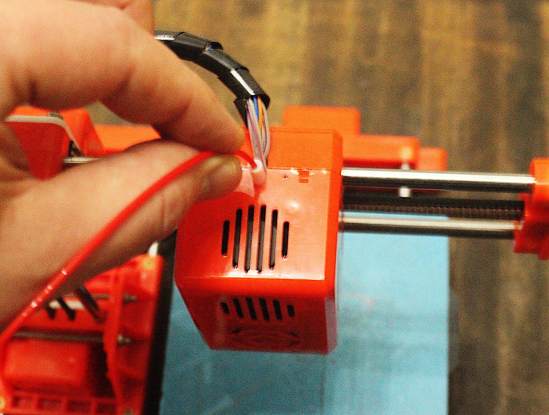
- Press Stop In/Out Filament as soon the filament comes out of the nozzle, or the filament is released from the extruder.
Make sure the nozzle is clean and no filament is sticking out, before you offset the printer head to X: 0, Y: 0, Z: 0 by choosing Auto home.
Use a piece of paper or a tweezers to remove any filament that sticks out. Do it before it cools down, as it will be more difficult to remove it by then.
Now that the filament is in, and the printing bed is leveled, lets print!
6.3. Print via SD
Use a SD card
Check, if you have enough filament in your printer. Is it the color you want to use?
- Go through the menu as follows >> Prepare >> Auto home.

This will set your printers head to X: 0, Y: 0, Z: 0, which is in the corner on the bottom Left.
- Stick in your SD card with the .gcode file of your sliced object.

- Go to >> Print from SD >> your_object.gcode. your_object.gcode represents the filename of your file.

- Click on your file.
And up it goes!
- The printer nozzle will heat up to the temperature you choose, and start printing.
- You can pause or stop the print in case something happens.
6.4. Print via USB (Linux, Win, Mac)
Use Pronterface to control printer
In this section, you will learn how to use Pronterface to control your printer directly connected to a PC/Laptop via USB.
Download Pronterface in case it is not installed yet.
-
You need to connect your printer via USB to your Laptop/PC first.
-
If you use our Moogle Offline Server Distribution use Menu >> Education >> Pronterfaceto start Pronterface.

If the printer has been recognized automatically, you should see an address (e.g. /dev/ttyUSB0) beside Port.
- Press the Connect button. You should get a message in Pronterface console at the right side panel.

You should be now able to move the printer head of your printer using the arrow symbols in Pronterface.
- Import your G-Code file of your object, that you save in your slicer software. To do that, press Load File in top panel.

- To start your print, press Printin top panel.

Tip: Click above the Temperature Monitor window to increase its size.

Each printed path will be shown in your preview window (here in red)

That's it! Easy...is it not!?
One more tip: In case you use another printer, check on your printer settings under Settings >> Options**


6.5. Print via USB (Android)
Use GCodePrintr on an Android Tablet
This section will show you how to use an Android Tablet as printer control device.
Setup:
- First and foremost you will need an adapter, that makes it possible to connect your printer to a mini usb socket on your tablet.
One example of an adapter:

- Next, you will need to buy this software in Google Play, and install it on your device:
- Now connect your printer to your tablet, and start GCodePrintr

- Now press the Gear symbol in the left panel to open Settings.

- First, lets setup the printer settings by pressing Settings >> Printer

- Press Bed size, and change it to 100.
- Press OK.

- Press Heatbed Temperature Preset 1, and type in 185.
- Press OK.
- Press Heatbed Temperature Preset 2, and type in 210.
- Press OK.
- Press Heatbed Temperature Preset 3 / Max Temperature, and type in 230.
- Press OK.

- Now press on Material, and press PLA (1.25g/cm3).

- Use the backward triangle symbol 2 times to get back to Settings.
- Then press Communication.

- Press on Printer Connection Type, and choose USB-OTG.

- Go back, then click on Baud rate for USB OTG.
- Choose 115200.

That's about it! The printer should work now properly under control of GCodePrintr!
- Press on the folder icon in the left panel to import your file.

- Search and select your .gcode file.
This is different to Prusa Slicer. You will need a .gcode file, not the .stl file.
If you only have the .stl go to "4.2.1 Use kiri:moto website to slice objects", and take it from there!

As soon the objects gcode is imported, the software will start to simulate the printing.
- Press the printer icon in the right side panel.
This will open the printer control panel.

- Press Connection Test to see if your printer is connecting to your tablet correctly.
You sould get a message in your console on the right side, that the printer is now connected.
Also the "i" section indicates the connection with "Ready to print".

- Now move the temperature slide up, to start heating up the nozzle to 210 degrees Celsius.
The nozzle temperature is indicated on the right side as second line beneath the console.
- When the temperature is reached, press the printing icon to start the printing process.

- Press the print icon now on the left side of the screen to close the printer control panel.

The preview is now in "Print Mode", which shows you the printing process graphically.

After the print is finished a Pop-up window will appear.

That is it! I hope you will have some great fun in printing your designs!
6.6. After Print
- After the print is finished, take of the magnetic print bed surface with the blue tape on it, and bend it. It makes it easier to remove it from it.
- If you used support material, you will get it off your object by using a miniature pocket pliers.
